Ш power switch (p. 11, 19), 2] display window (p. 54), 5] counter reset button (p. 13) – Sony CCD-TR514 User Manual
Page 48: 6] title button (p. 27), Ш steady shot mode switch (p. 28), 8] eyecup (p. 15), 9] viewfinder lens adjustment lever (p. 12), Ijol battery mounting surface (p. 9), 331 lanc c control jack, In 0 (headphones) jack (p. 19)
Attention! The text in this document has been recognized automatically. To view the original document, you can use the "Original mode".
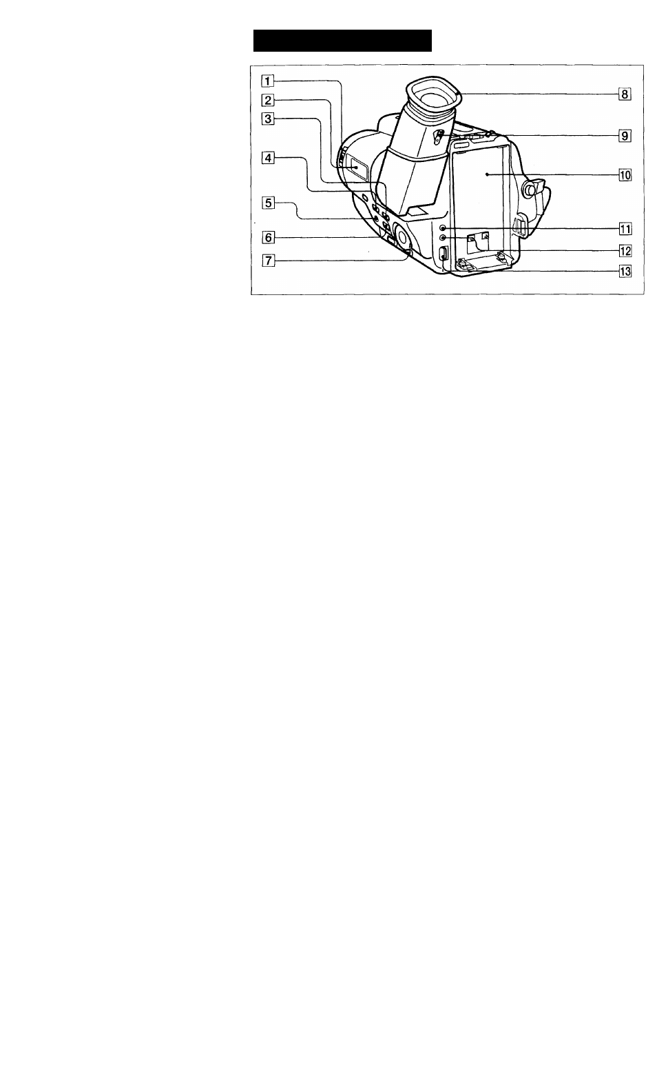
Identifying the Parts
Ш POWER switch (p. 11, 19)
[2] Display window (p. 54)
CCD-TR99 only
[3] TIME(NEXT) button (p. 23, 33)
g] DATE(+) button (p. 23, 33)
[5] COUNTER RESET button (p. 13)
[6] TITLE button (p. 27)
Ш
STEADY SHOT mode switch (p. 28)
CCD-TR99/TR814 only
[8] Eyecup (p. 15)
[9] Viewfinder lens adjustment lever (p. 12)
CCD-TR99/TR714 only
iJOl Battery mounting surface (p. 9)
331 LANC
C
control jack
Connect the LANC
C
connecting cable to a wired remote control unit such as an editing
controller. In this case, set the COMMANDER mode to OFF (p. 29). ft stands for Local
Application Control Bus sytem. The C control jack is used for controlling the tape transport of
video equipment and peripherals cormected to it. This jack has the same function as the
connectors indicated as CONTROL L or REMOTE.
in 0 (headphones) jack (p. 19)
CCD-TR99 only
n ВАТТ (battery) release knob (p. 9)
48