Sound Anchors DL5 system User Manual
Page 13
Page 13 of 28
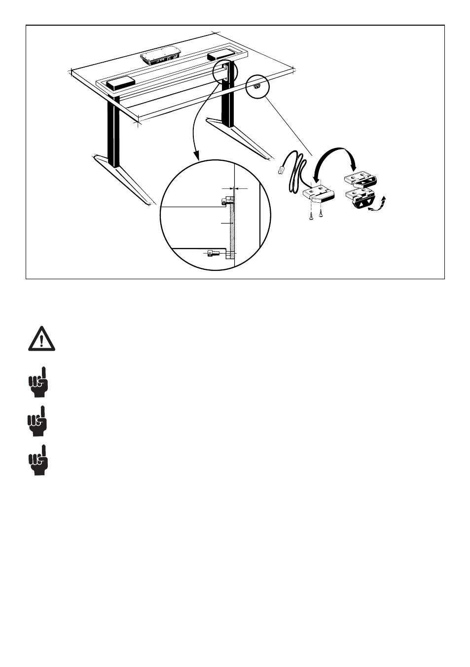
Figure 3
(Example of how to mount a 2 parallel DESKLINE
®
DL5/DL6 system)
Min. 1 mm
Cross bar
DL5/
DL6
Mounting bracket
To avoid damage of the lifting unit there must be min. 1 mm space between the end of the screw for
the mounting bracket and the surface of the lifting unit (see fi gure 1). The use of any longer screws
will come into contact with the inner parts. This will result in an irregular operation or even damage
the lifting unit.
The DESKLINE
®
DL5/DL6 system can only be used in push applications with the motor housing
mounted upwards.
Placement of a monitor directly above the motor housing may cause malfunction of the monitor.
Magnets inside the motor may interrupt the picture on the monitor depending on the distance and
type of monitor. If this is the case the problem may be solved by placing an iron plate/tube or another
magnetic material, somewhat larger than the motor housing, between the motor, and the tabletop.
The end-stop system in the DB6 is based on a buffer system meaning that you must be aware of the
lengths when initialising. The products must be able to drive:
Inwards direction: built-in dimension - tolerances – 5 mm
Outwards direction: built-in dimension + stroke length + tolerances + 5 mm