Page 8, Hedv40 - figure 6, Hedv25 - figure 6 – Louisville Tin and Stove HEDV254A User Manual
Page 8: Figure 7 figure 8
INSTALLATION - CONTINUED
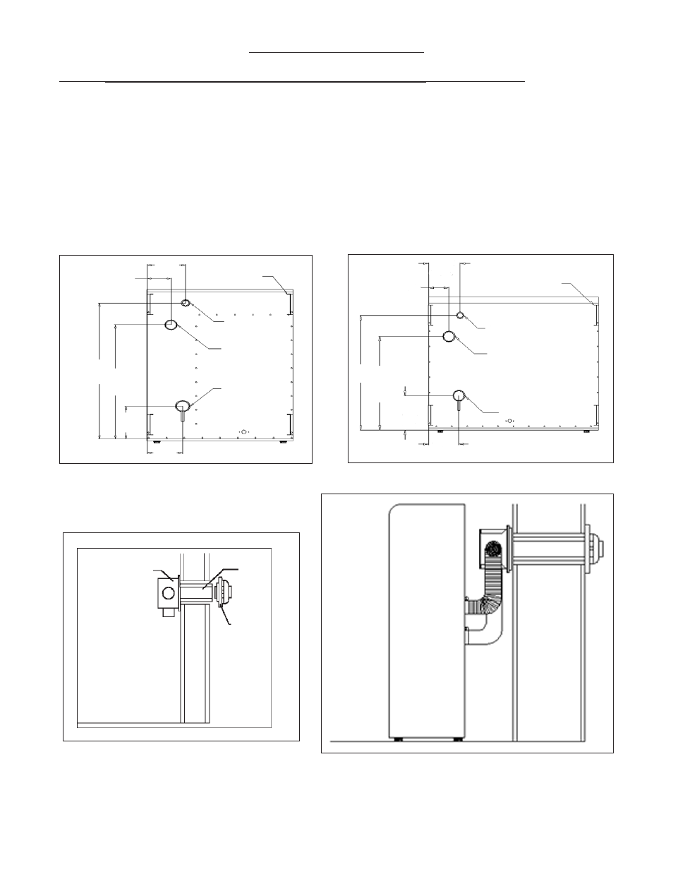
STEP 3 INSTALLING VENT SYSTEM 5” - 32” WALL THICKNESS (12.7 cm - 81.3 cm)
a)
Use only factory supplied parts. Do not attempt to modify in any way. To do so could cause a system
imbalance resulting in poor performance and/or unsafe operating conditions.
b)
Slide collection box pipes through cutout and secure collection box to inside wall. Anchors (not sup-
plied)
may be required. (See Figure 5).
c)
From outside house, mark collection box pipes and cut off 1/2” beyond outside wall.
d)
Slide vent cap pipes onto collection box pipes and push in until flange is flush against house. Secure vent
cap assembly to outside wall with a slight downward slope. This will prevent water from entering and
allow condensation to drain. Caulk around the edges of the vent cap mounting plate. NOTE: It may
be necessary to build a metal or wood frame to provide a flat surface for the mounting plate to be flush
against or to attain the 5” minimum wall thickness.
Page 8
FIGURE 5
6-1/4”
(15.9 cm)
Trim Kit Brackets
Gas Inlet
Air Intake
Flue Outlet
6-1/8”
(15.6 cm)
4-1/8”
(10.2 cm)
2
5
”
(63.5 cm)
20-1
1/16”
(52.5 cm)
7-9/16”
(19.2 cm)
HEDV40 - Figure 6
6-3/8”
(16.2 cm)
4”
(10.2 cm)
29-5/8”
(75.2 cm)
25-1/16”
(63.7 cm)
7-9/16”
(19.2 cm)
5-7/8”
(14.9 cm)
Trim Kit Brackets
Gas Inlet
Air Intake
Flue Outlet
HEDV25 - Figure 6
Collection Box
Assembly
Vent Cap
Assembly
Vent Cap
Mounting
Plate
FIGURE 7
FIGURE 8