Page 7 – Louisville Tin and Stove HEDV254A User Manual
Page 7
INSTALLATION
Failure to follow these instructions carefully could result in poor performance, property damage, personal injury,
or death.
STEP 1. LOCATE VENT OPENING (Requires 3-1/2” diameter wall opening)
a)
Select area on wall where heater will be installed. Using template (packed with heater) mark shaded area
where hole can be cut and to locate the wall brackets. (See Figure 4).
b)
Locate studs on each side of this area.
c)
Mark location for 3-1/2” diameter hole between studs. Hole should be offset to miss studs. (See Fig. 4).
d)
Check outside wall at this location for proper clearances around vent cap. (See Fig. 1).
e)
Cut vent openings into both the inside and outside walls, being sure to maintain level across both open-
ings.
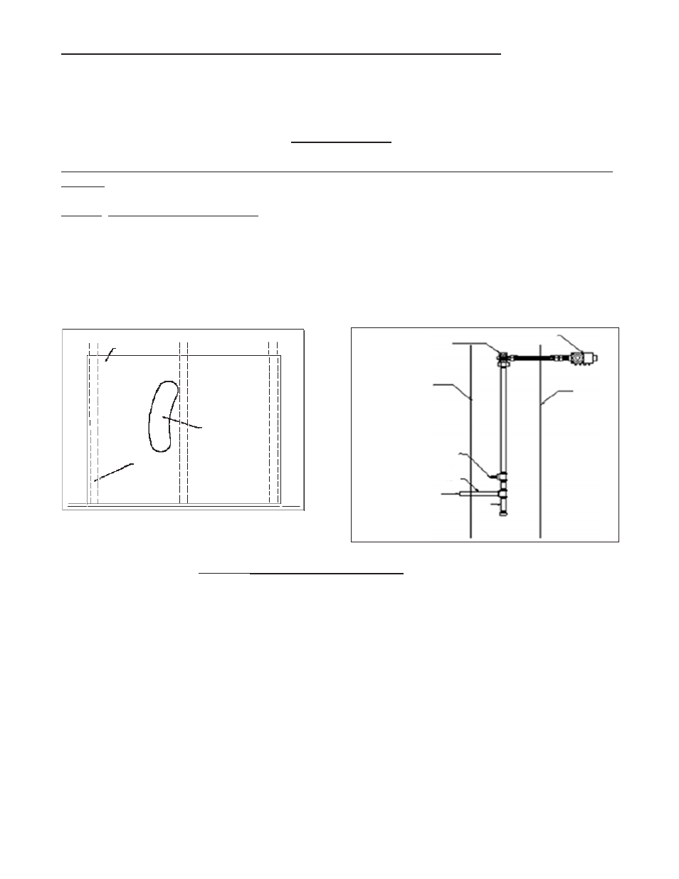
STEP 2. ROUGH-IN GAS SUPPLY (See Figure 5)
Install at least 3/8” gas supply line. Contact local gas supplier if any questions.
Install a drip leg in gas supply line immediately upstream from the gas connection to heater (see local
codes), and provide a 1/8” N.P.T. plugged tapping, accessible for test gauge connection and an indi-
vidual manual shut off valve accessible within room where heater is installed. (See Figure 5). The
heater and its individual shut off valve must be disconnected from the gas supply piping system during
any pressure testing of that system at test pressures in excess of 1/2 psig (3.5Pa). The heater must be
isolated from the gas supply piping system by closing its individual manual shut off valve during any
pressure testing of the gas supply piping system at test pressures equal to or less than 1/2 psig (3.5Pa).
Test all connections for leaks using a soapy solution. NEVER USE AN OPEN FLAME TO TEST FOR
LEAKS.
The maximum inlet gas supply pressure for Natural or L.P./Propane gas is 1/2 p.s.i. or 14” w.c.
The minimum inlet gas supply pressure for the purpose of adjustment is 4.5” w.c. for Natural gas or 11.0” w.c. for
L.P./Propane gas.
Page 7
FIGURE 5
Gas Valve
Back of
heater
Wall
Gas Supply
Drip
Leg
Manual shut-off valve
must be accessible in
room where heater is
installed
Manual shut off valve with
1/8” NPT plugged tapping
Must be accessible in room
where heater is installed
3/8” Black iron pipe
Template
Shaded
Area
Wall
Studs
16” O.C.
FIGURE 4
ATTENTION ALL CANADIAN CONTRACTORS/INSTALLERS: Before installing
this heater into a multi-family hi-rise exceeding four stories, contact the local building
code inspector to verify the building construction complies with the Progressive Col-
lapse requirements as listed in the National Building Code of Canada 2005.