Back-panel features and indicators, Figure 1, For more information on – Dell PowerEdge 1850 User Manual
Page 10
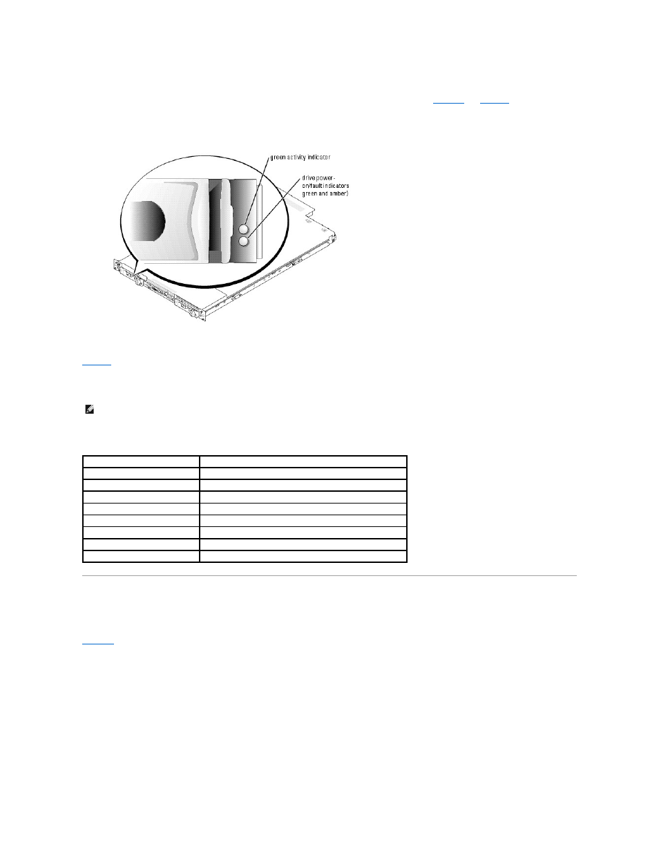
If RAID is activated, two indicators on each of the hard-drive carriers provide information on the status of the SCSI hard drives. RAID can be enabled either by
using ROMB on the optional riser card (when available) or by using a RAID card connected to the backplane. See
and
. The SCSI backplane
firmware controls the drive power-on/fault indicator.
Figure 1-2. SCSI Hard-Drive Indicators
lists the drive indicator patterns. Different patterns are displayed as drive events occur in the system. For example, if a hard-drive fails, the "drive
failed" pattern appears. After the drive is selected for removal, the "drive being prepared for removal" pattern appears, followed by the "drive ready for
insertion or removal" pattern. After the replacement drive is installed, the "drive being prepared for operation" pattern appears, followed by the "drive online"
pattern.
Table 1-3. Hard-Drive Indicator Patterns
Back-Panel Features and Indicators
shows the controls, indicators, and connectors located on the system's back panel.
Figure 1-3. Back-Panel Features and Indicators
NOTE:
If RAID is not activated, only the "drive online" indicator pattern appears. The drive-activity indicator also blinks when the drive is being
accessed.
Condition
Indicator Pattern
Identify drive
The green power-on/fault indicator blinks four times per second.
Drive being prepared for removal
The green power-on/fault indicator blinks two times per second.
Drive ready for insertion or removal Both drive indicators are off.
Drive being prepared for operation The green power-on/fault indicator is on.
Drive predicted failure
The power-on/fault indicator slowly blinks green, amber, and off.
Drive failed
The amber power-on/fault indicator blinks four times per second.
Drive rebuilding
The green power-on/fault indicator blinks slowly.
Drive online
The green power-on/fault indicator is on.