Video connector, Mouse connector – Dell PowerEdge 4600 User Manual
Page 7
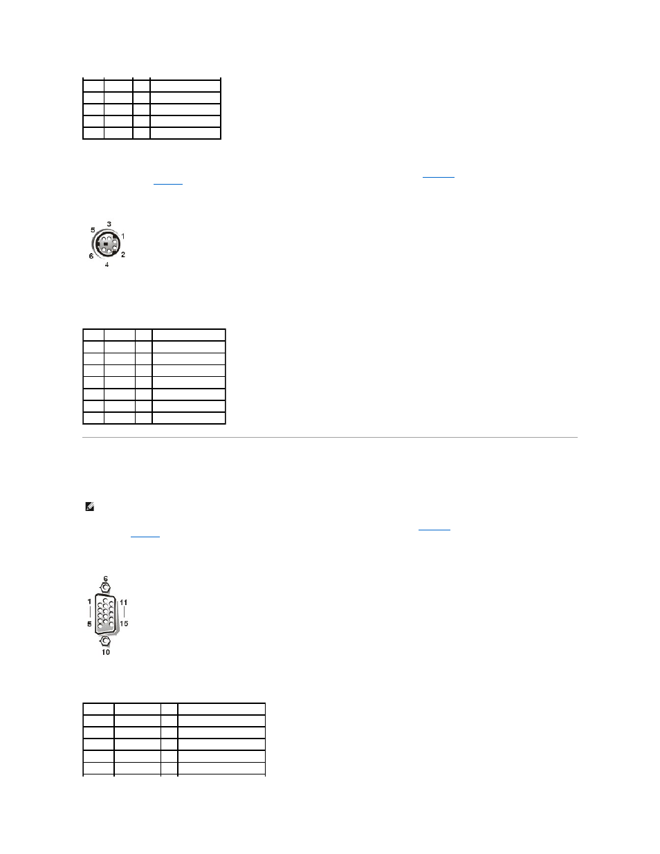
Mouse Connector
If you reconfigure your hardware, you may need pin number and signal information for the mouse connector.
illustrates the pin numbers for the
mouse connector, and
defines the pin assignments and interface signals for the mouse connector.
Figure B-5. Pin Numbers for the Mouse Connector
Video Connector
The system uses a 15-pin high-density D-subminiature connector on the back panel for attaching a video graphics array (VGA)-compatible monitor to your
system. The video circuitry on the system board synchronizes the signals that drive the red, green, and blue electron guns in the monitor.
illustrates the pin numbers for the video
defines the pin assignments and interface signals for the video connector.
Figure B-6. Pin Numbers for the Video Connector
3
GND
N/A Signal ground
4
FVcc
N/A Fused supply voltage
5
KBCLK
I/O Keyboard clock
6
NC
N/A No connection
Shell N/A
N/A Chassis ground
Table B-4. Mouse Connector Pin
Assignments
Pin
Signal
I/O Definition
1
MFDATA
I/O Mouse data
2
NC
N/A No connection
3
GND
N/A Signal ground
4
FVcc
N/A Fused supply voltage
5
MFCLK
I/O Mouse clock
6
NC
N/A No connection
Shell N/A
N/A Chassis ground
NOTE:
Installing a video card automatically disables the system's integrated video subsystem.
Table B-5. Video Connector Pin Assignments
Pin
Signal
I/O Definition
1
RED
O
Red video
2
GREEN
O
Green video
3
BLUE
O
Blue video
4
NC
N/A No connection
5–8, 10 GND
N/A Signal ground