Drac/mc module features, Drac/mc, Module features – Dell POWEREDGE 1855 User Manual
Page 14: Drac/mc version 1.1 (or later) module
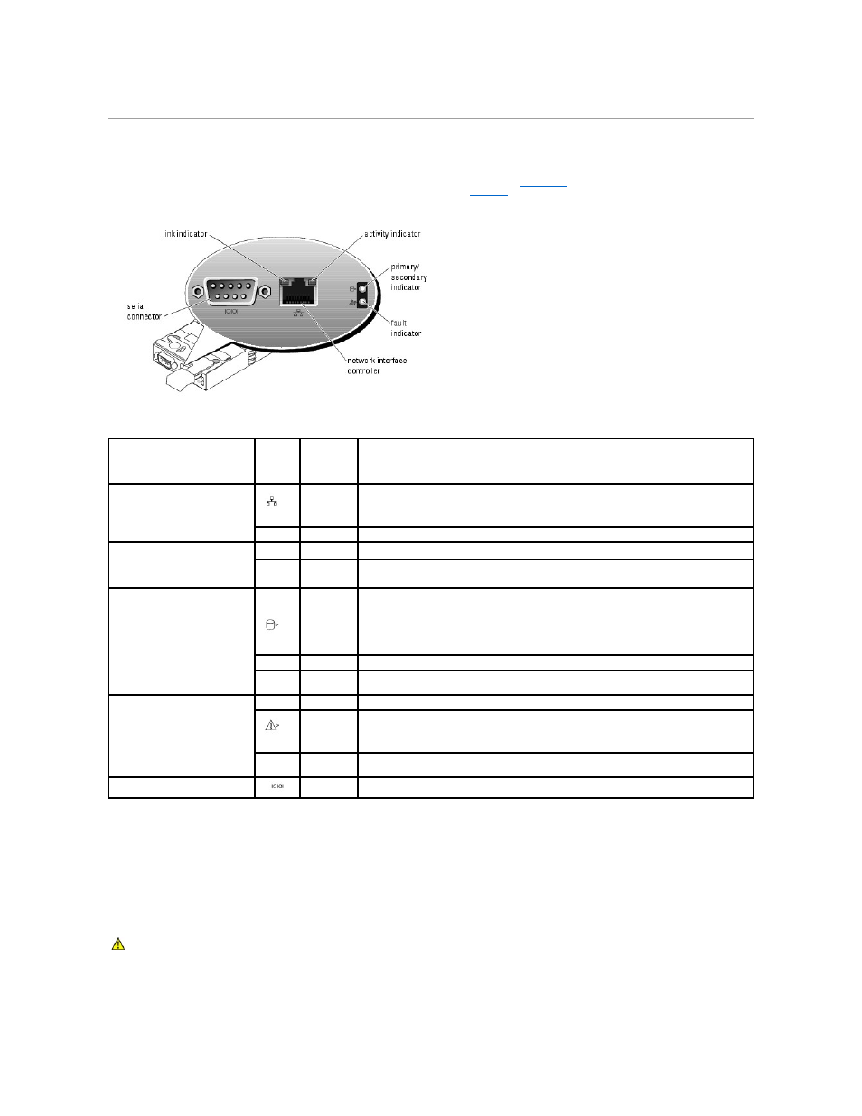
DRAC/MC Module Features
The DRAC/MC provides serial and Ethernet management ports, a status indicator when redundant DRAC/MCs are installed (when available), and status
indicators for the DRAC/MC and for the link to the system's onboard network interface controller (see
). See the documentation for the DRAC/MC
module for specific information on serial port redirection of server modules and switches.
provides information about the status indicators.
Figure 1-11. DRAC/MC Module Features
Table 1-9. DRAC/MC Module Indicators
DRAC/MC Version 1.1 (or Later) Module
If you have a DRAC/MC version 1.1 (or later) module installed, ensure that you read that product's readme.txt file. It contains updated information, including
system indicator behavior in certain conditions.
Important I/O Configuration Considerations
Unless your system is configured according to these guidelines, do not perform any of the following actions:
Indicator Type
Icon
Activity
Indicator
Indicator Code
Network interface controller link
indicator
Off
LAN is not linked.
Green
LAN is linked.
Network interface controller
activity indicator
Off
LAN is not active.
Amber
blinking
Indicates that the system DRAC/MC and the LAN are communicating.
Primary/secondary indicator
Off
The DRAC/MC is a backup for the master DRAC/MC.
NOTE:
For information on availability of dual (redundant) configurations for the DRAC/MC, see
www.dell.com.
Green
The DRAC/MC is active for system management.
Green
blinking
The DRAC/MC is in special or manufacturing mode.
Fault indicator
Off
The DRAC/MC is operating normally.
Amber
In a single (nonredundant) configuration, this DRAC/MC failed. See your Installation and
Troubleshooting Guide for detailed information.
Amber
blinking
In a dual (redundant) configuration (when available), this DRAC/MC failed. See your Installation
and Troubleshooting Guide for detailed information.
Serial connector
None
Used for a serial connection with a null modem cable.
CAUTION:
Data loss can result if you perform certain actions on a system in which the I/O bays have not been configured correctly. Specifically,
bay 2 should have an I/O module installed only if an identical module is present in bay 1, and bay 4 should have an I/O module installed only if
an identical module is present in bay 3. Except in these cases (or in a case where you temporarily need to swap a failed I/O module in bay 1 or
3), bays 2 and 4 should be unoccupied.