Figure 1, Shows a sample configuration and, Table 1 – Dell POWEREDGE 1855 User Manual
Page 10: Provides information about the back, Power supply indicator
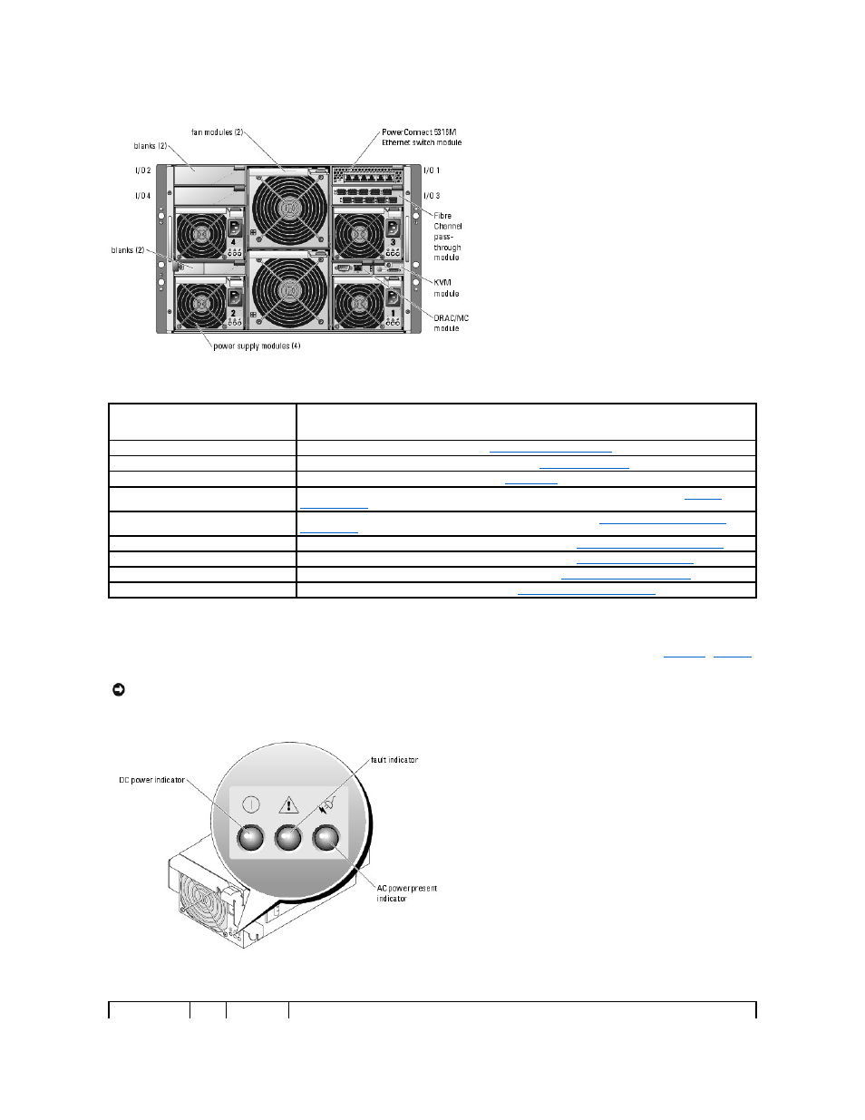
Figure 1-5. Back-Panel Features
Table 1-4. Back-Panel Features
Power Supply Indicator
lists the power supply indicator codes.
Figure 1-6. Power Supply Indicators
Table 1-5. Power Supply Indicator Codes
Component
Indicator Description
Power supply modules
Provide information about power status (see "
").
Fan modules
Provide information about status of the system fans (see "
KVM module
Provides information about the KVM module (see "
").
DRAC/MC module
Provides information about system status, system management status, and port status (see "
PowerConnect™ 5316M Ethernet switch
module
Provides information about the 10/100/100 BASE-T network status (see "
Fibre Channel pass-through module
Provides information about the Fibre Channel network status (see "
Fibre Channel Pass-Through Module
Fibre Channel switch module
Provides information about the Fibre Channel network status (see "
Infiniband pass-through module
Provides information about the Infiniband network status (see "
Infiniband Pass-through Module
Gb pass-through module
Provides information about the network status (see "
Gb Ethernet Pass-through Module
").
NOTICE:
2100-W power supply modules require 170-264 V to operate; 1200-W power supply modules (systems sold prior to April 2005) require 180–
264 V to operate. If they are plugged into 110-V electrical outlets, the power supply modules will not power up.