Display assembly, Removing the display assembly – Dell Latitude D420 User Manual
Page 15
Back to Contents Page
Display Assembly
Dell™ Latitude™ D420 Service Manual
Removing the Display-Panel Brackets
1.
Follow the instructions in
Before You Begin
.
2.
Remove the hinge cover (see
Hinge Cover
).
3.
Remove the keyboard (see
Keyboard
).
4.
Remove the internal card with Bluetooth® wireless technology (see
Internal Card With Bluetooth® Wireless Technology
).
Removing the Display Assembly
1.
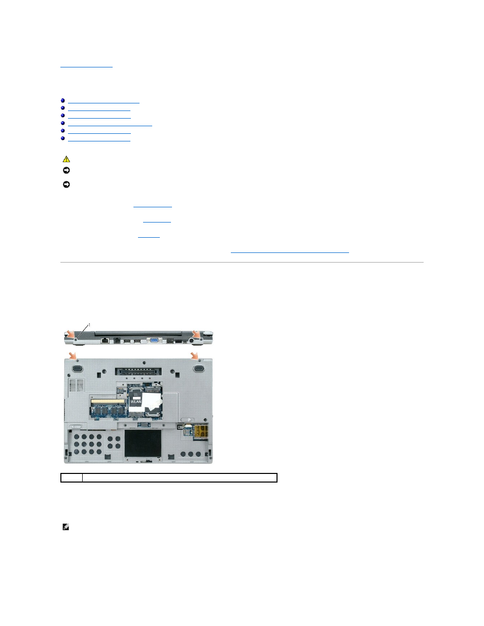
Remove the two M2.5 x 5-mm left and right hinge screws from the back of the computer.
2.
Turn the computer upside down and remove the two M2.5 x 5-mm screws labeled "D" from the computer base.
3.
Remove the antenna cables from the WLAN and Mobile Broadband Mini-Cards, if applicable.
4.
Turn the computer over topside up and open the display approximately 180 degrees so that it lies flat against your work surface.
5.
Carefully dislodge the Mini-Card antenna cables from their routing guides and pull the cables with their connectors through the system board so that
they are clear of the computer base.
CAUTION:
Before you begin any of the procedures in this section, follow the safety instructions in the Product Information Guide.
NOTICE:
To avoid electrostatic discharge, ground yourself by using a wrist grounding strap or by periodically touching an unpainted metal surface (such
as the back panel) on the computer.
NOTICE:
You must remove the display assembly before you remove the palm rest.
1
M2.5 x 5-mm screws (4)
NOTE:
Ensure that any plastic sleeves that protect unconnected Mini-Card connectors do not slide off.