Serial port connector, Parallel port connector – Dell PowerVault 770N (Deskside NAS Appliance) User Manual
Page 24
The integrated serial ports use 9-pin D-subminiature connectors on the back panel. These ports support devices such as
external modems, printers, plotters, and mice that require serial data transmission (the transmission of data one bit at a time
over one line).
Most software uses the term COM (for communications) plus a number to designate a serial port (for example, COM1 or
COM2). The default designations of your system's integrated serial ports are COM1 and COM2.
The integrated parallel port uses a 25-pin D-subminiature connector on the system's back panel. This I/O port sends data in
parallel format (where eight data bits, or one byte, are sent simultaneously over eight separate lines in a single cable). The
parallel port is used primarily for printers.
NOTE:
Using this system as a print server is not supported.
Most software uses the term LPT (for line printer) plus a number to designate a parallel port (for example, LPT1). The default
designation of the system's integrated parallel port is LPT1.
Port designations are used, for example, in software installation procedures that include a step in which you identify the port
to which a printer is attached, thus telling the software where to send its output. (An incorrect designation prevents the
printer from printing or causes scrambled print.)
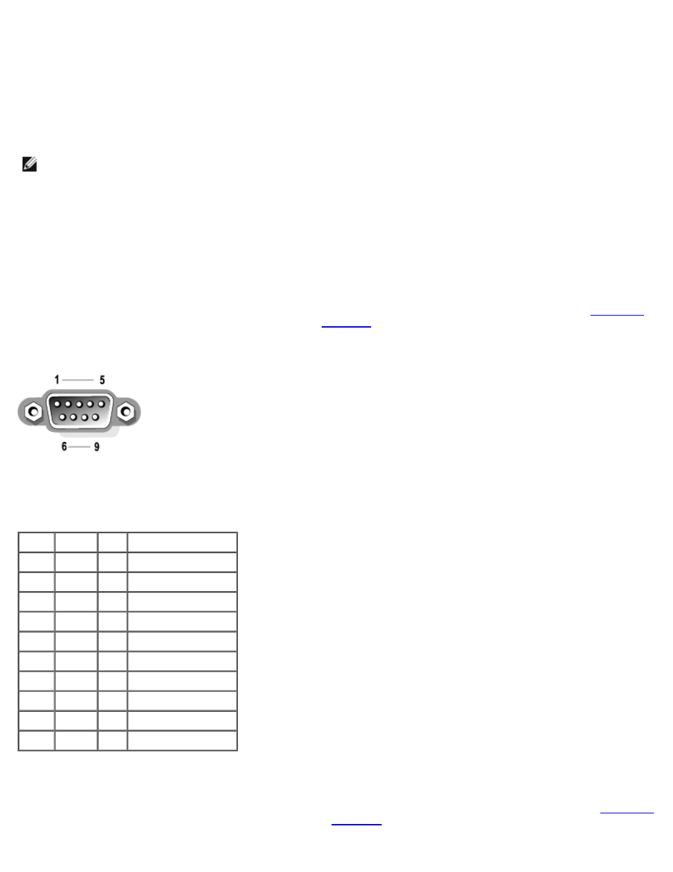
Serial Port Connector
If you reconfigure your hardware, you may need pin number and signal information for the serial port connector.
illustrates the pin numbers for the serial port connector and
defines the pin assignments and interface signals for
the serial port connector.
Figure B-2. Pin Numbers for the Serial Port
Table B-1. Serial Port Pin Assignments
Pin
Signal I/O Definition
1
DCD
I
Data carrier detect
2
SIN
I
Serial input
3
SOUT
O
Serial output
4
DTR
O
Data terminal ready
5
GND
N/A Signal ground
6
DSR
I
Data set ready
7
RTS
O
Request to send
8
CTS
I
Clear to send
9
RI
I
Ring indicator
Shell N/A
N/A Chassis ground
Parallel Port Connector
If you reconfigure your hardware, you may need pin number and signal information for the parallel port connector.
illustrates the pin numbers for the parallel port connector and