Video connector, Usb connectors – Dell PowerEdge 600SC User Manual
Page 7
Video Connector
The system uses a 15-pin high-density D-subminiature connector on the back panel for attaching a video graphics array (VGA)-compatible monitor to the
system. The video circuitry on the system board synchronizes the signals that drive the red, green, and blue electron guns in the monitor.
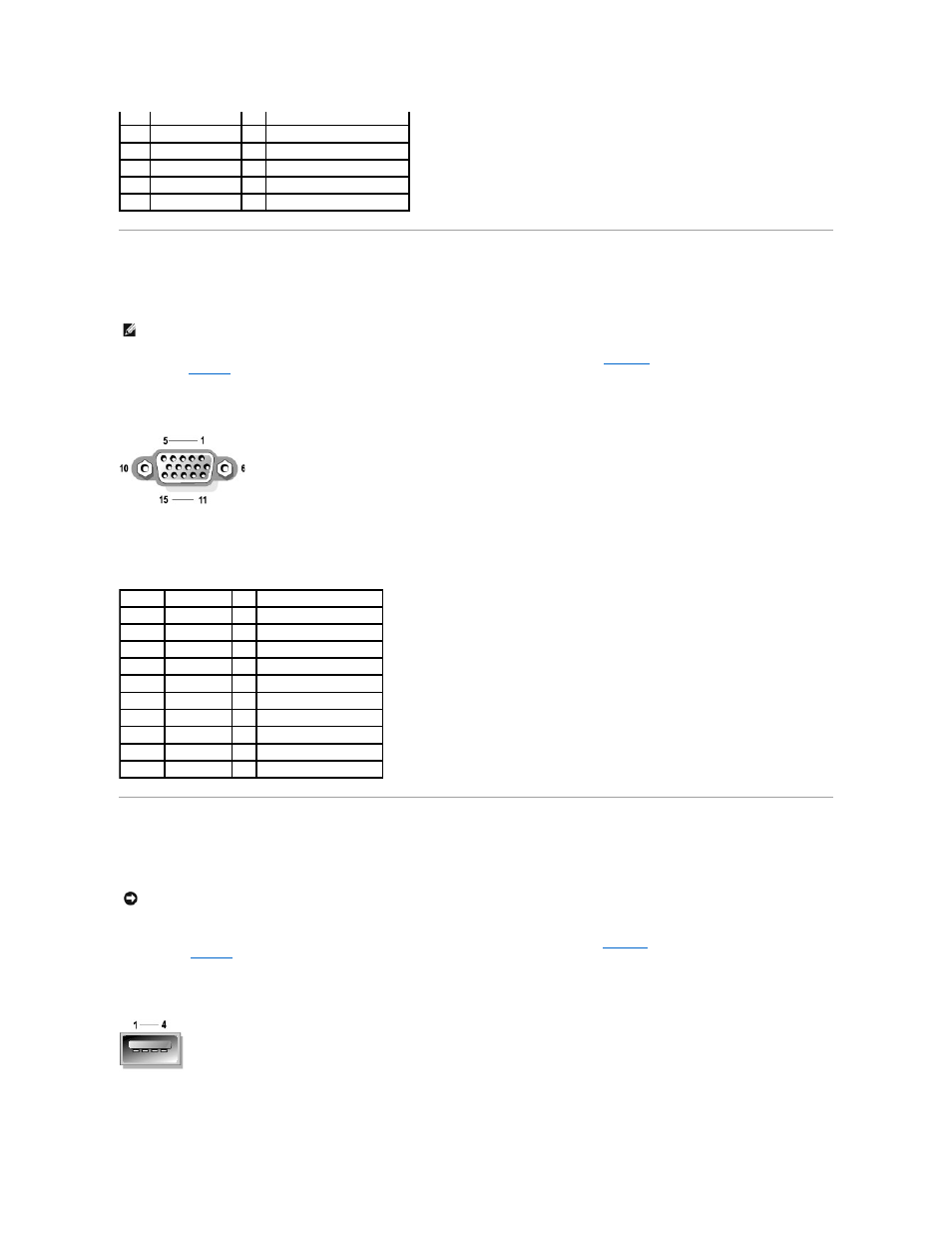
illustrates the pin numbers for the video
defines the pin assignments and interface signals for the video connector.
Figure B-5. Video Connector Pin Numbers
USB Connectors
Your system contains two USB connectors for attaching USB-compliant devices. USB devices are typically peripherals such as mice, printers, keyboards, and
system speakers.
If you reconfigure your hardware, you may need pin number and signal information for the USB connectors.
illustrates the pin numbers for the USB
defines the pin assignments and interface signals for the USB connectors.
Figure B-6. USB Connector Pin Numbers
2
NC
N/A No connection
3
GND
N/A Signal ground
4
FVcc
N/A Fused supply voltage
5
KBCLK or MFCLK
I/O Keyboard clock or mouse clock
6
NC
N/A No connection
Shell N/A
N/A Chassis ground
NOTE:
Installing a video card automatically disables the system's integrated video subsystem.
Table B-4. Video Connector Pin Assignments
Pin
Signal
I/O Definition
1
RED
O
Red video
2
GREEN
O
Green video
3
BLUE
O
Blue video
4
NC
N/A No connection
5–8, 10 GND
N/A Signal ground
9
VCC
N/A Vcc
11
NC
N/A No connection
12
DDC data out O
Monitor detect data
13
HSYNC
O
Horizontal synchronization
14
VSYNC
O
Vertical synchronization
NOTICE:
Do not attach a USB device or a combination of USB devices that draw a maximum current over 500 milliamperes (mA) per channel or +5 volts
(V). Attaching devices that exceed this threshold may cause the USB ports to shut down. See the documentation that accompanied the USB devices for
their maximum current ratings.