Microprocessor module, Removing the microprocessor module, Installing the microprocessor module – Dell Inspiron 510m User Manual
Page 10
Back to Contents Page
Microprocessor Module
Dell™ Inspiron™ 510m Service Manual
Removing the Microprocessor Module
1.
Follow the instructions in "
Preparing to Work Inside the Computer
."
2.
Remove the
keyboard
.
3.
Remove the
microprocessor thermal-cooling assembly
.
4.
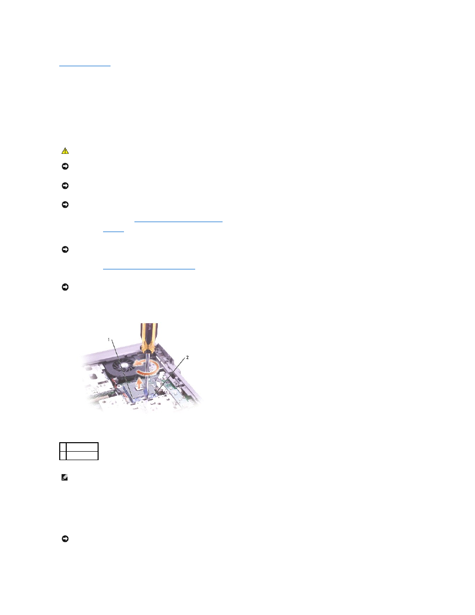
To loosen the ZIF socket, use a small, flat-blade screwdriver and rotate the ZIF-socket cam screw counterclockwise until it comes to the cam stop.
5.
Lift out the microprocessor module.
Installing the Microprocessor Module
CAUTION:
Before performing the following procedures, read the safety instructions in your Owner's Manual.
NOTICE:
To avoid electrostatic discharge, ground yourself by using a wrist grounding strap or by periodically touching an unpainted metal surface (such
as the back panel) on the computer.
NOTICE:
Do not touch the processor die. Press and hold the microprocessor down on the substrate on which the die is mounted while turning the cam
screw to prevent intermittent contact between the cam screw and microprocessor.
NOTICE:
To avoid damage to the microprocessor, hold the screwdriver so that it is perpendicular to the microprocessor when turning the cam screw.
NOTICE:
To ensure maximum cooling for the microprocessor, do not touch the heat transfer areas on the microprocessor thermal-cooling assembly. The
oils in your skin reduce the heat transfer capability of the thermal pads.
NOTICE:
When removing the microprocessor module, pull the module straight up. Be careful not to bend the pins on the microprocessor module.
1 pin-1 corner
2 ZIF socket
NOTE:
The ZIF-socket cam screw secures the microprocessor to the system board. Take note of the arrow on the ZIF-socket cam screw.
NOTICE:
Ensure that the cam lock is in the fully open position before seating the microprocessor module. Seating the microprocessor module properly in
the ZIF socket does not require force.