Dell PowerEdge R820 User Manual
Page 5
5
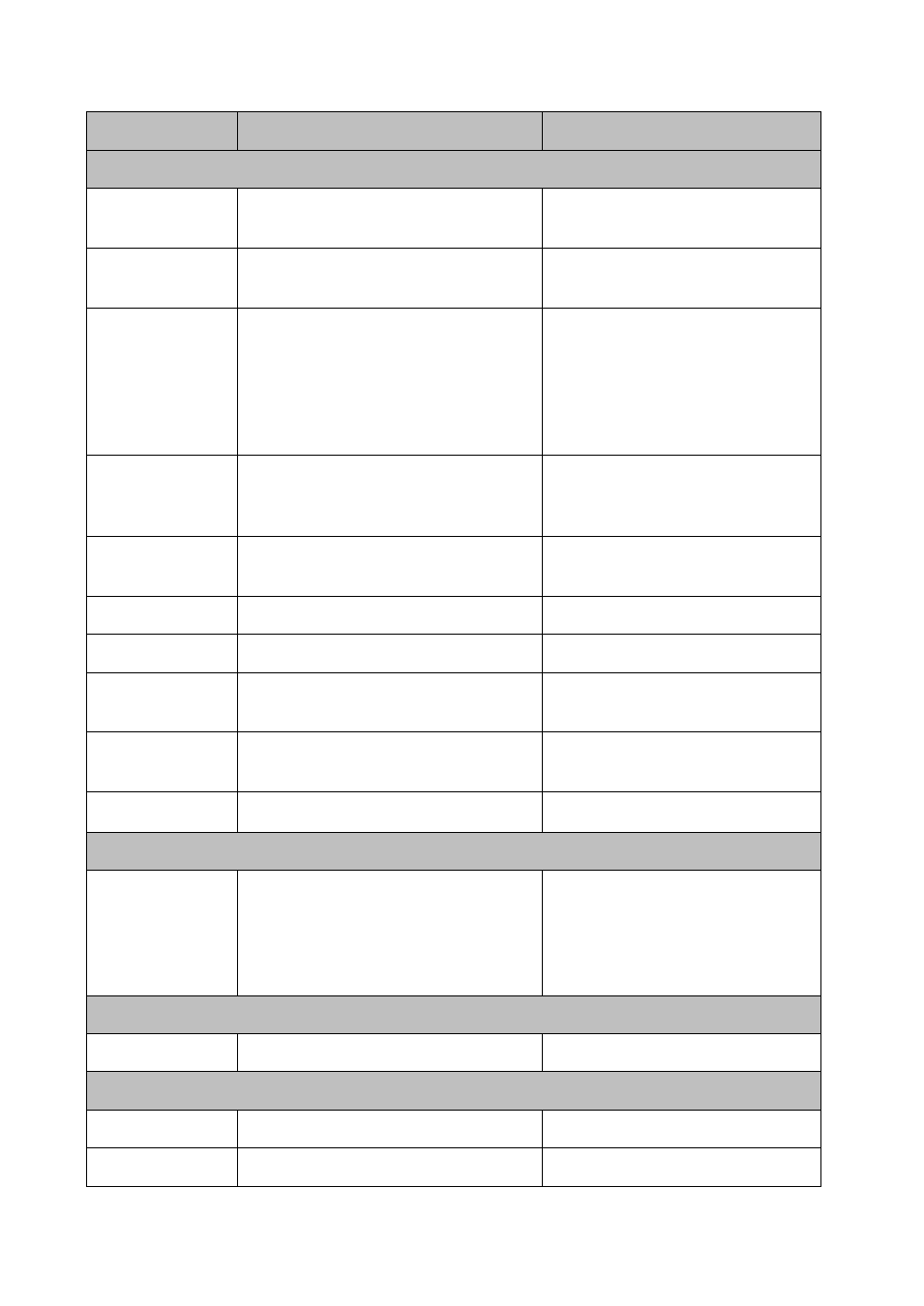
Item
Purpose? (e.g. boot code)
How is data input to this memory?
Planer
PCH Internal CMOS
RAM
Real-time clock and BIOS configuration
settings
BIOS
BIOS SPI Flash
Boot code, system configuration information,
UEFI environment, Flash descriptor, ME
SPI interface via iDRAC
iDRAC SPI Flash
iDRAC Uboot (bootloader), server
management persistent store (i.e. IDRAC
MAC Address, iDRAC boot variables), lifecycle
log cache, virtual planar FRU and EPPID, rac
log, system event log, JobStore, iDRAC Secure
boot code,
SPI interface via iDRAC
BMC EMMC
Operational iDRAC FW, Lifecycle Controller
(LC) USC partition, LC service diags, LC OS
drivers, USC firmware
NAND Flash interface via iDRAC
CPU Vcore and VSA
Regulators
Operational parameters
Once values are loaded into register
space a command writes to NVMEM.
System CPLD RAM
Not utilized
Not utilized
System Memory
System OS RAM
System OS
Internal USB Key
General purpose USB key drive
USB interface via PCH. Accessed via
system OS
Trusted Platform
Module (TPM)
Storage of encryption keys
Using TPM Enabled operating systems
PEM FRU
FRU
I2C interface via iDRAC
Power Supplies
PSU FW
Power Supply operation, power management
data and fault behaviors
Different vendors have different utilities
and tools to load the data to memory. It
can also be loaded by Dell Update
Package from LC or OS (Windows and
Linux)
8x2.5" Backplane
SEP internal flash
Firmware
16x2.5" Backplane
Flash memory
Firmware
Common Flash memory Interface (CFI)
Expander FRU image FRU
I2C interface via iDRAC