Jefferson direct vent /natural vent gas heater, Side wall termination assembly – Century Jefferson User Manual
Page 17
17
Jefferson Direct Vent /Natural Vent Gas Heater
30004177
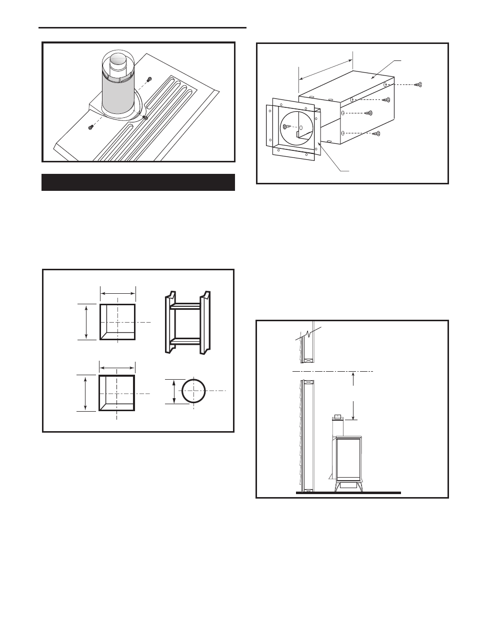
2. Measure the wall thickness and cut the wall sleeve
sections to proper length (MAXIMUM 12”). Assemble
the sleeve with the #8 sheet metal screws supplied.
Attach the firestop plate to the sleeve end with the
holes. (Fig. 23) NOTE: The wall sleeve is required
in combustible walls only.
3. Install the Wall Firestop/Sleeve assembly into the
wall cutout and fasten the firestop to the wall cutout
framing members. (Fig. 23)
Side Wall Termination Assembly
1. Locate the vent opening on the wall. Refer to Page
7, Figure 5, to determine the opening centerline.
It may be necessary to first position the stove and
measure to find the hole location. Depending on
whether the wall is made of combustible materi-
als, cut the opening to the size shown in Figure
22. Combustible wall openings must be framed as
shown in Figure 22.
VO584-100
Vent Opening
2/99 djt
9³⁄₈”
(240mm)
7¹⁄₂”
9³⁄₈”
(240mm)
Framing Detail
Combustible Wall
Noncombustible
Wall
VO584-100
Fig. 22 Locate vent opening.
CFM System
DuraVent
System
10”
(254mm)
10”
(254mm)
For DuraVent pipe only: Install vent pipe by align-
ing the locking system together, sliding the pipes
together and twisting clockwise.
•
Install 90° elbow. Twist lock as before.
•
Slide the wall plate over horizontal run before at-
taching the horizontal run to the elbow. Fasten wall
plate to wall.
4. For CFM Vent Pipe only: If necessary, measure
to determine the vertical length (X) of pipe required
from the adapter pipe to the wall cutout centerline,
including a 2” overlap at the joint. (Fig. 24) use a
hacksaw or tin snips to trim the pipe as needed.
ZCS103
Zero Clearance Sleeve
& Firestop
12/6/99 djt
12”
(305mm)
Max. Length
Sleeve
#8 Sheet
Metal Screws
Firestop
ZCS103
Fig. 23 Assemble the wall sleeve and firestop.
X
ST214
measure vertical vent
12/6/99 djt
ST214
Fig. 24 Determine the vertical pipe length.
ST356
dura vent
attach outer assy
4/7/00 djt
ST356
Fig. 21 Simpson Dura-Vent - install outer adapter pipe.
5. Install first the inner then the outer straight pipe
section(s), trimmed end down, to the point of the el-
bow. Drill 3 holes through each joint and fasten with
sheet metal screws.