40" electric range installation instructions, Junction box location, Range placement – FRIGIDAIRE FPEF4085KF User Manual
Page 6: Range installation, Excessive weight hazard, Preparation
6
40" ELECTRIC RANGE INSTALLATION INSTRUCTIONS
Follow instructions for
the type of installation you have
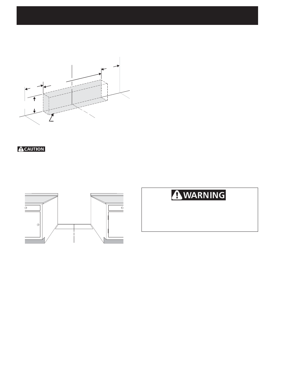
Center
Line of
Range
Locate Electrical Hook-up
Inside Shaded Area
Center
Line of
Range
10"
(25.4 cm)
10"
(25.4 cm)
7" Max.
(17.8 cm Max.)
20"
(50.8 cm)
FLOOR
WALL
Center
Line of
Range
Figure 8
Junction Box Location
Locate junction box as shown in Figure 7.
If a service cord is used, the wall receptacle should be
located in accordance with the dimensions below.
Range Placement
To eliminate the risk of burns or fi re by
reaching over heated surface units, cabinet storage space
located above the range should be avoided. If cabinet
storage space is to be provided, the risk can be reduced
by installing a range hood that projects horizontally a
minimum of 5" (12.7 cm) beyond the bottom of the
cabinet.
Figure 7
If range will be installed with a cabinet on both
sides, draw a center line on the fl oor between the
cabinets (see fi gure 8). If back of range will not be
fl ush with the wall (the location of the outlet may not
allow the range to be positioned against the wall), draw
a line on the fl oor where the back edge of the range will
be. Now install anti-tip brackets (see "Anti-Tip Bracket
Installation, page 8).
If range will be installed with a cabinet on one side
only, move the range into fi nal position. Draw a line on
the fl oor along the side of the range that is not against
the cabinet. If back of range will not be fl ush with
the wall (the location of the outlet may not allow the
range to be positioned against the wall), draw a line
on the fl oor where the back edge of the range will be.
Now install anti-tip brackets (see "Anti-Tip Brackets
Installation", page 8).
If range will not be installed against a cabinet, move
range into fi nal position. Mark on the fl oor along both
sides of the range. If back of range will not be fl ush
with the wall (the location of the outlet may not allow
the range to be positioned against the wall), draw a
line on the fl oor where the back edge of the range will
be. Now install anti-tip brackets (see "Anti-Tip Brackets
Installation", page 8).
Range Installation
NOTE:
1. The back of the range may be installed directly
against the rear wall of the structure.
2. These ranges conform to U.L. requirements for "0"
spacing from the range to adjacent vertical walls
above the countertop level. However, to reduce
possible scorching of vertical walls and to minimize
potential fi re hazards under abnormal surface unit
use conditions such as high heat or no pans, a
minimum of 2" (5.1 cm) spacing should be provided
on both sides of the cooktop.
3. If a wall is present on the left side of range, allow a
minimum of 2 3/4" (7 cm) to open the auxiliary door.
Excessive Weight Hazard
• Use 2 or more people to move and install
range.
• Failure to follow this instruction can result in
back or other injury.
Preparation
1. Put on safety glasses and gloves. Remove oven racks
and parts package from inside the oven. Remove
shipping materials, tape and protective fi lm from the
range.
2. Take 4 cardboard corners from the carton. Stack
one on top of another. Repeat with other 2 corners.
Place corners lengthwise on the fl oor in back of the
range to support range.
3. Firmly grasp the range and gently lay it on its back
on the cardboard corners.
4. Remove the 4 shipping bolts from the skid. Discard
skid.
5. Lay a large piece of cardboard in front of the range.
Carefully stand the range upright on cardboard.
6. Adjust the leveling legs to a point where the range
base does not touch the fl oor.