Uni-max, Lms-uni), Installation guide – LaserMax LMS-UNI-MAX RED User Manual
Page 2: Warning
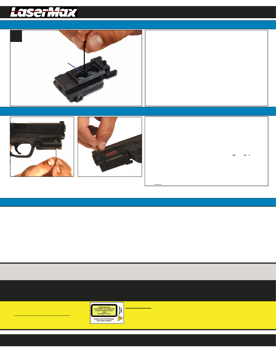
To sight in your laser, insert the Adjustment Tool into
one of the small alignment ports on the outside of the
Laser Housing.
Fine tune your laser alignment by slowly turning the
Adjustment Tool, then checking your laser position
against your fixed sights and your POI(Point of Impact).
The Uni-Max comes factory set for a modulated (pulsed) beam for
higher visibility. To change to a continuous wave (steady on) beam,
follow these simple steps:
g
installation guide
Uni-Max
®
(LMS-UNI)
Changing The Laser Mode
1.800.527.3703
installation guide
1.800.527.3703
01785-0-19
REV F 12/10
Remove the Battery Cover.
Insert Adjustment Tool into the beam selection port.
(See Figure g)
Slowly turn the Adjustment Tool clockwise until you feel
resistance. Do not over tighten.
Reassemble and confirm that your beam is now
continuous wave (steady on).
To return to the modulated (pulsed) laser mode, simply
insert Adjustment Tool into the beam selection port and
make three counterclockwise turns. Do not remove the
set screw from the beam selection port.
Beam Selection Port
(do not remove internal set screw)
You can easily fine tune your laser to accommodate any weapon
platform, type of ammunition or shooting distance.
Limited Warranty
LASERMAX, INC.
3495 WINTON PLACE
ROCHESTER, NY 14623 USA
Patent No. 7,421,818; other patents pending
LMS-UNI
RED/ORANGE LASER SIGHT
CLASS 3R VISIBLE LASER PRODUCT
Output: <5 mW
Wavelength: 635 nm
Complies with 21CFR1040 per laser notice 50 (2001)
Reminder:
Aiming laser beam at moving vehicles including boats, aircraft, trains, and construction equipment may be illegal. Check current applicable laws and follow them accordingly.
WARNING:
Avoid direct exposure
to beam.
Registration of your product is required in order to receive warranty service. Log on to www.lasermax.com to
fill out the registration form.
LaserMax, Inc. laser products, except expendable parts, are warranted to be free from defects in material and workmanship for a period of one year from the date of purchase submitted
through warranty registration at www.lasermax.com. Expendable parts shall be defined as batteries, springs, and replaceable plastic parts. Expendable parts of some models have definite
life expectancies. They should be replaced as recommended to protect the laser and preserve your warranty. This warranty shall benefit, and may be enforced only by the initial purchaser
of the laser system and is not transferable. Warranty is limited solely to repairing or replacing the part(s), at the discretion of LaserMax, Inc.; which proves to be defective during the war-
ranty period. Parts and equipment replaced under warranty will not be returned. Parts and equipment repaired under warranty will be covered for the remaining portion of the original war-
ranty period. This warranty does not apply to equipment or parts which upon inspection by LaserMax, Inc. are determined by LaserMax, Inc. to have become defective or unworkable due
to abuse, mishandling, misuse, alteration, negligence, improper installation or maintenance, damage resulting from use of springs not supplied with laser, damage resulting from repair or
attempted repair by anyone other than LaserMax, Inc. or a repair facility authorized by LaserMax, Inc., or other causes beyond the control of LaserMax, Inc. All returns must have factory
labeling present and legible. All returns require a return authorization number available from our Warranty Department at 1-800-LASER-03. The hours of operation are from 9 a.m. to 5 p.m.
EST, Monday through Friday.
LASERMAX, INC. DISCLAIMS LIABILITY FOR INCIDENTAL AND CONSEQUENTIAL DAMAGES FOR BREACH OF ANY EXPRESS OR IMPLIED WARRANTY. ANY IMPLIED WARRANTY OF
MERCHANTABILITY OR FITNESS FOR A PARTICULAR PURPOSE, WITH RESPECT TO THE LASERMAX, INC. LASER PRODUCT IS FOR A PERIOD OF ONE YEAR FROM DATE OF
PURCHASE. THIS WARRANTY GIVES YOU SPECIFIC LEGAL RIGHTS, AND YOU MAY ALSO HAVE OTHER RIGHTS WHICH VARY FROM STATE TO STATE.
Important:
This alignment should be done at a minimum distance
of 10 yards. A one-quarter (1/4) turn equals approximately 3 inches
at 10 yards
Warning:
Do not turn Adjustment Tool more than one complete
turn from factory position. This may cause damage to the Uni-Max
and may void your warranty.
The hole at the side adjusts windage
(horizontal alignment). A clockwise turn
(front, to top, to bottom) shifts laser to
the left.
The hole at the bottom adjusts elevation
(vertical alignment). A clockwise turn
(left side, to front, to right side of fire-
arm) shifts laser down.
SPARE PARTS LIST:
LMS-UNI-RG:
Removable Rail Grip
LMS-UNI-CS:
Clamping Screw (Part: B)
-includes spring
Battery Cover (Part: C),
Flat Head Screw (2)(Part: D),
Adjustment Tool (Part: F)
LMS-UNI-AS:
Activation Switch (Part: G)
LMS-2X357:
Batteries: 357(2) (Part: E)
LMS-UNI-SKN:
(Service Kit)
Aligning The Laser For POA/POI
NOTE:
When installing Uni-Max for the first time, a slight shift in alignment may be
noticed after firing, due to settling. Recheck alignment after firing a few magazines and
readjust if necessary.
ACCESSORIES:
LMS-UNI-MAS-10:
Momentary Activation Switch (10” Cord)
LMS-ADP-SHOTGUN:
Rail Adapter for 1” shotgun mag tube
LMS-HKADP-C:
Rail Adapter for H&K USP Compact
LMS-UNI-MAS-6:
Momentary Activation Switch (6” Cord)
LMS-ADP-SIGMA:
Rail Adapter for S&W Sigma Series
LMS-HKADP-F:
Rail Adapter for H&K USP Full Size