Hudson Robotics RapidWash User Manual
Page 3
3
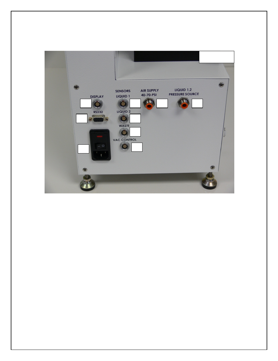
Section 1 - Setup
1.1- Tubing and Connections
Figure 1
1-
Touch Screen Display Connection
2-
RS-232 Communication Connection
3-
AC Inlet For Power Cable
4-
Liquid 1 Level Sensor
Position around Liquid 1 bottle close to bottom (See Figure 2)
5-
Liquid 2 Level Sensor
Position around Liquid 2 bottle close to bottom (See Figure 2)
6-
Waste Level Sensor
Position around Waste bottle close to top (See Figure 3)
7-
Vac Control
Output for remote control for external vacuum
8-
Air In
From air source 40-70 PSI to rear of Rapid Wash, this for the
internal pressure regulator and optional plate gripper
9-
Pressure source for Liquid 1 and 2
1/4" OD tube connected between Liquid 1/ liquid 2 bottles and rear
of RapidWash (See Picture 2)
1
4
5
6
7
8
9
2
3
Rear Panel