Blocking the intake, Fig. 3, Fig. 4 fig. 5 – FLO~PRO 301008 User Manual
Page 5
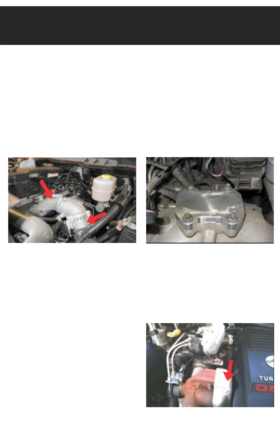
STEP 5:
Ensure the mounting surface on the intake
elbow is clear of any gasket material.
STEP 6:
Unplug the electrical connector from the
backside of the throttle valve. The throttle
valve is shown in Fig. 3.
STEP 7:
Install the intake block-off (G) with supplied
bolts. (Fig. 4) Ensure both O-Rings are fully
seated.
STEP 8:
Remove heat shield from EGR bypass. This is
held in place by three 10mm nuts and two
8mm bolts. (Fig. 5)
Blocking the Intake
Fig. 3
Intake Elbow
Throttle Valve
Fig. 4
Fig. 5