Qm-md5x1 – Crestron electronic QM-MD5x1 User Manual
Page 7
Crestron QM-MD5x1
QuickMedia™ Matrix Switcher/Mixer
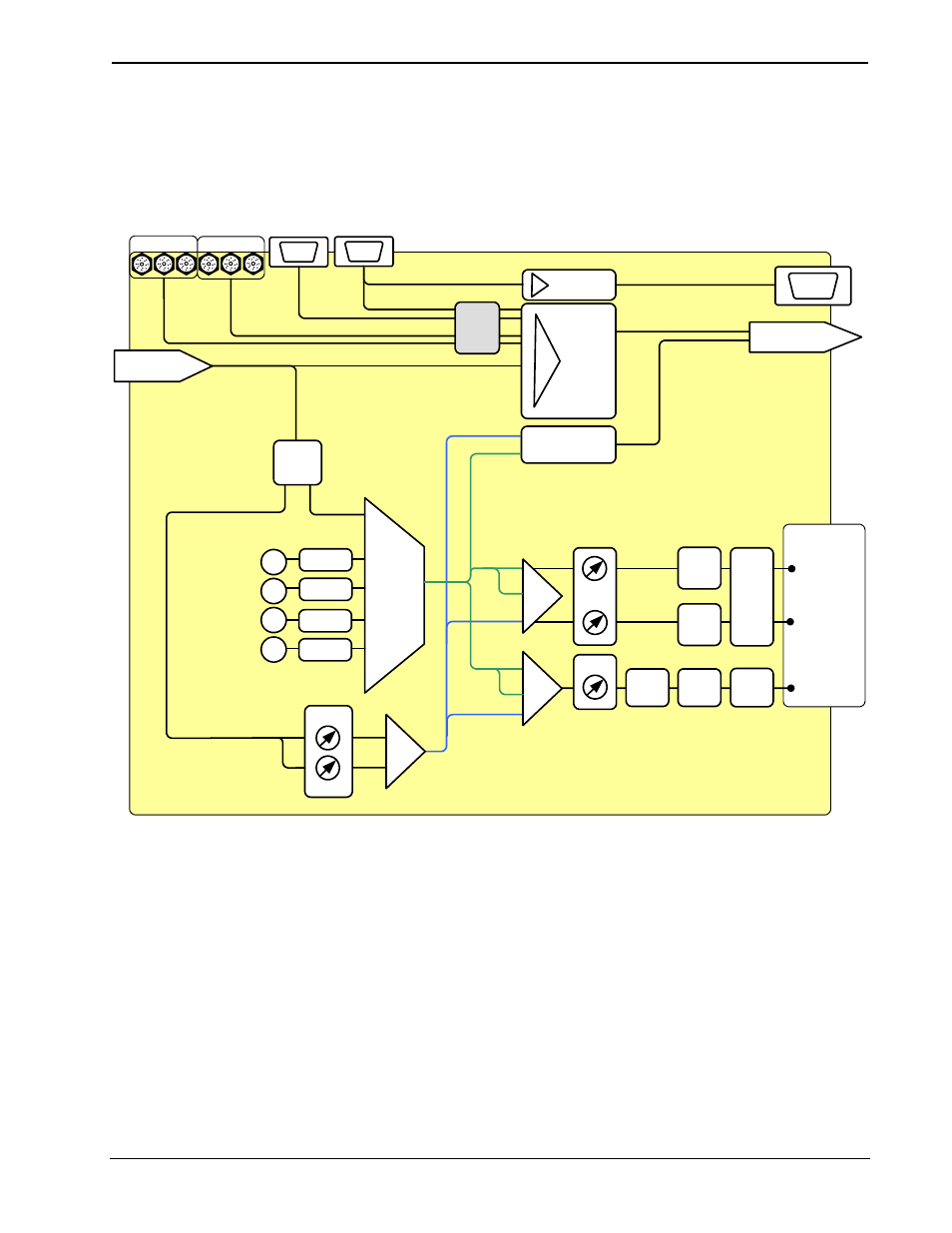
The following diagram represents the switching and mixing capabilities of the
MD5x1. The MD5x1 can be operated locally (local mode) using buttons on the front
panel, or remotely from a control system (system mode). For more information, refer
to “Operating Modes” on page 58.
Functional Diagram of the QM-MD5x1
Buffer
RGB Monitor
Passthrough
QM OUT*
QM IN 5
Program/
Mic
Splitter
QM Audio Output
Combiner
5 X 1 Video
Crosspoint
RGB 3
RGB 4
Video
Sense
EQ
Local
Stereo
Audio
Inputs
5 X 1
Stereo
Switcher
A/D
A/D
A/D
A/D
1
2
3
4
Mute
Program L
Program R
Mute
Speech
AUDIO
OUT
D/A
D/A
D/A
Delay
Vol/EQ
Vol/EQ
Mix
Mix
L
L
R
R
Mic
Mic
Mic Mix
L+R
QM L+R
QM L+R
QM Mic
1 + 2
1
2
Video Inputs
QM-MD5X1
*
ALL QM MICROPHONE MIX SIGNALS FROM THE QM-MD5X1 ARE SENT OUT ON THE
MIC 1 CHANNEL OF THE QM OUTPUT. THERE ARE NO MICROPHONE SIGNALS
ON THE MIC 2 CHANNEL OF THE QM OUTPUT.
Mix
Operations Guide - DOC. 6300
QuickMedia™ Matrix Switcher/Mixer: QM-MD5x1
• 3