EcoPure EPASF1 User Manual
Page 9
9
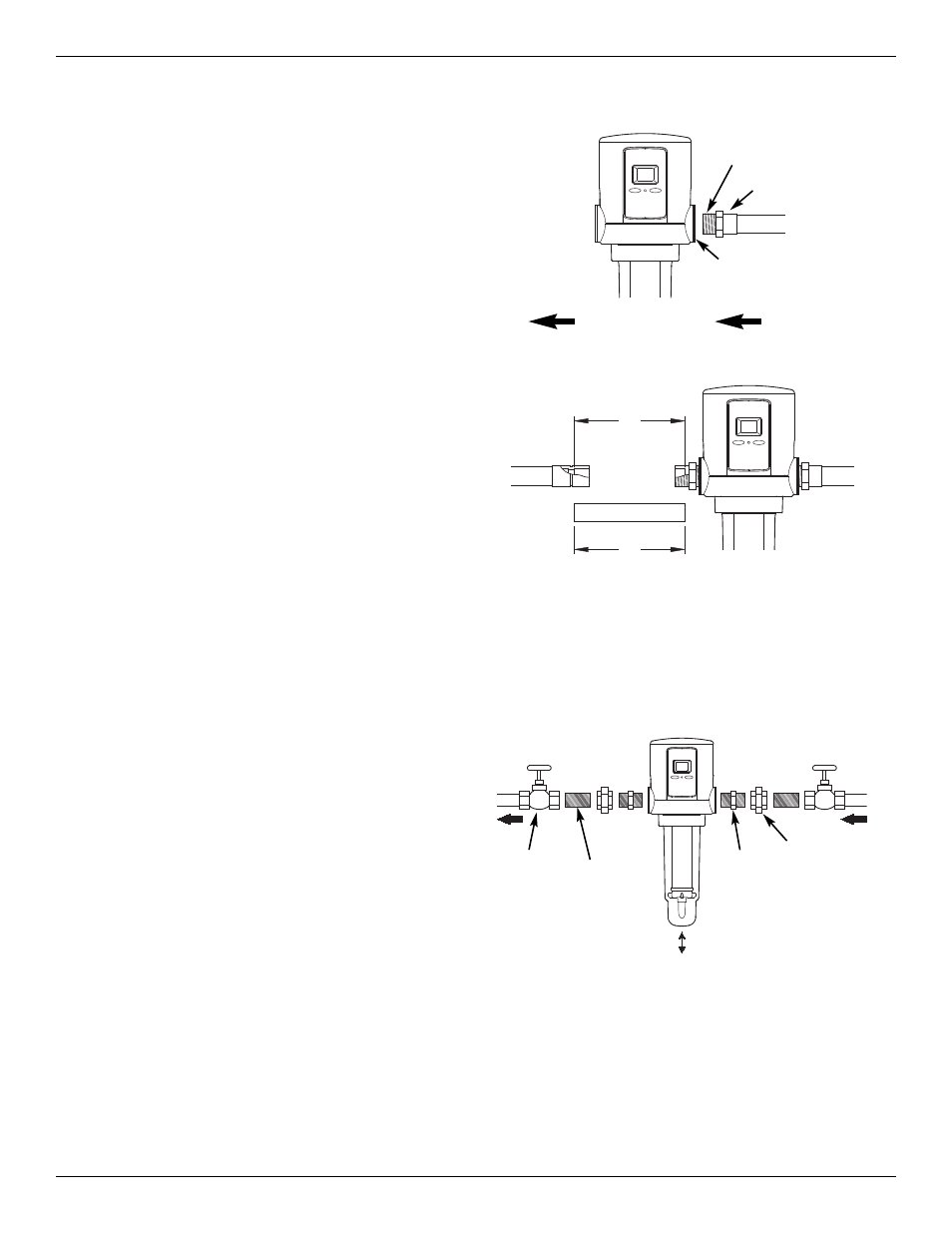
FIG. 15
D
D
FIG. 16
IN
OUT
WATER FLOW
Sweat Adaptor
Apply at least 4 wraps
of Teflon Tape
Mounting Bracket
(Optional)
7. Turn a sweat adaptor fitting into the other side of the
filter head and hand tighten only. Using a tape
measure or ruler, measure the distance “D” as
shown in Figure 16. Mark this same dimension on a
length of copper pipe. Cut the length of pipe.
8. Remove the sweat adaptor fitting from the filter
head and solder to the cut length of pipe.
9. After it cools, apply at least 4 wraps of Teflon tape to
the threads on the sweat adaptor fitting. Apply flux
and place the pipe end of the soldered assembly
into the straight connector. Then, turn the adaptor
end into the filter head and tighten.
10. Solder both sides of the straight connector.
NOTE: Read the “Grounding Information” on Page 6,
and comply with the instructions if required to
maintain continuity.
11. Do not turn the water supply back on yet. Go to
“Complete the Installation” on Page 10 and fol-
low the instructions to install the drain hose.
Installation - Type B (continued)
Installation - Type C
INSTALLATION USING THREADED PIPE & FITTINGS
MATERIALS & TOOLS NEEDED
=
Pipe threading tool
=
Pipe wrenches
=
Pipe joint compound
=
Union fittings
=
Pipe Nipples
INSTALL FILTER ON PIPE
1. Connect the filter housing as typically shown in
Figure 17. Use pipe joint compound on all external
threads. Do not turn pipe or fittings too tightly into
the filter head or you may break it. It is important to
have some linear movement in the house main
water pipe, as this will allow you to tighten union fit-
tings without damaging the filter head if pipe lengths
are not exact.
NOTE: If your installation will use the mounting brack-
et, position it correctly around the ASF before
installing inlet and outlet fittings. The bracket
can not be put on after the inlet and outlet fit-
tings are installed.
NOTE: Read the “Grounding Information” on Page 6,
and comply with the instructions if required to
maintain continuity.
2. Do not turn the water supply back on yet. Go to
“Complete the Installation” on Page 10 and fol-
low the instructions to install the drain hose.
FIG. 17
WATER
IN
WATER
OUT
IN
OUT
Optional
Shutoff
Valve (2)
1” Nipple
(2)
See Note in Figure 9
1” Hex
Nipple
(2)
Union
Fitting
(2)