Installation - type a (continued), Installation - type b – EcoPure EPASF1 User Manual
Page 8
MATERIALS & TOOLS NEEDED
=
2 sweat adaptors, 1” NPT x sweat end to fit your
main water pipe
=
Lead-free solder and flux
=
Soldering torch
=
Teflon tape
=
Sandpaper or emery cloth
=
Wrench, either open end (to fit sweat adaptor) or
adjustable jaw
INSTALL FILTER ON PIPE
CAUTION: Heat created when soldering can damage
the water filter’s plastic parts. Be sure to use the fol-
lowing procedure to protect the water filter.
1. IMPORTANT: Turn off the water supply to the main
pipe. Open a high and low faucet in the water sys-
tem to drain the pipe.
2. On the main water pipe, where you will install the fil-
ter, use a tubing cutter to remove a section of pipe
about 12" long. Use sandpaper or emery cloth to
thoroughly clean and remove all burrs and rough
edges, from both pipe ends.
NOTE: When soldering, use lead-free solder and flux
only. Be sure pipe and fittings are properly
cleaned.
3. Solder a sweat adaptor onto one of the pipe ends
(See Figure 14).
4. Place, but do not solder, a straight connector onto
the other pipe end (See Figure 14).
5. After it cools, apply at least 4 wraps of Teflon tape to
the threads on the sweat adaptor fitting (See Figure
15).
NOTE: If your installation will use the mounting brack-
et, position it correctly around the ASF before
installing inlet and outlet fittings. The bracket
can not be put on after the inlet and outlet fit-
tings are installed.
6. With the IN side of the water filter toward incoming
water, carefully, turn the filter head onto the sweat
adaptor fitting (See Figure 15). Do not cross-thread,
or overtighten and crack the filter head. If neces-
sary to provide clearance to rotate the filter head,
temporarily remove the sump / screen assembly.
continued on next page
FIG. 14
Straight
Connector
Sweat
Adaptor
8
Installation - Type A (continued)
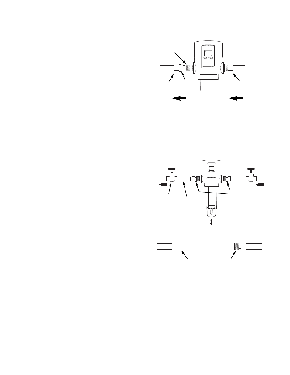
FIG. 12
WATER FLOW
IN
OUT
Nut
Nut
Fitting
Brass
Ferrule
8. With the IN side of the water filter toward incoming
water, spread the pipes apart and fit both pipe ends
into the compression fittings. Move a ferrule and
nut up to the fitting (See Figure 12). Then, turn on
and tighten the nut. Hold the fitting with one wrench
while tightening the nut with the other. Repeat on
the other side, again not overtightening.
NOTE: Read the “Grounding Information” on Page 6,
and comply with the instructions if required to
maintain continuity.
9. Do not turn the water supply back on yet. Go to
“Complete the Installation” on Page 10 and fol-
low the instructions to install the drain hose.
Installation - Type B
INSTALLATION USING SOLDERED COPPER FITTINGS
FIG. 13
WATER
IN
WATER
OUT
IN
OUT
Adaptor, 1” NPT
Sweat (Apply at
least 4 wraps of
Teflon Tape)
Optional
Shutoff
Valve (2)
1” Copper
Pipe, as
required
See Note in Figure 9