Installation, Application 1, Application 2 – Dynalco SW-100 Speed Switch User Manual
Page 9: Troubleshooting
INSTALLATION
The unit is equipped with a universal mounting foot for attachment to
standard DIN style mounting rails, including G profile rail according to
EN50035 - G32 , and top hat (T) profile rail according to EN50022 - 35 x
7.5 and 35 x 15. The unit should be installed in a location that does not
exceed the maximum operating temperature and provides good air
circulation. Placing the unit near devices that generate excessive heat
should be avoided.
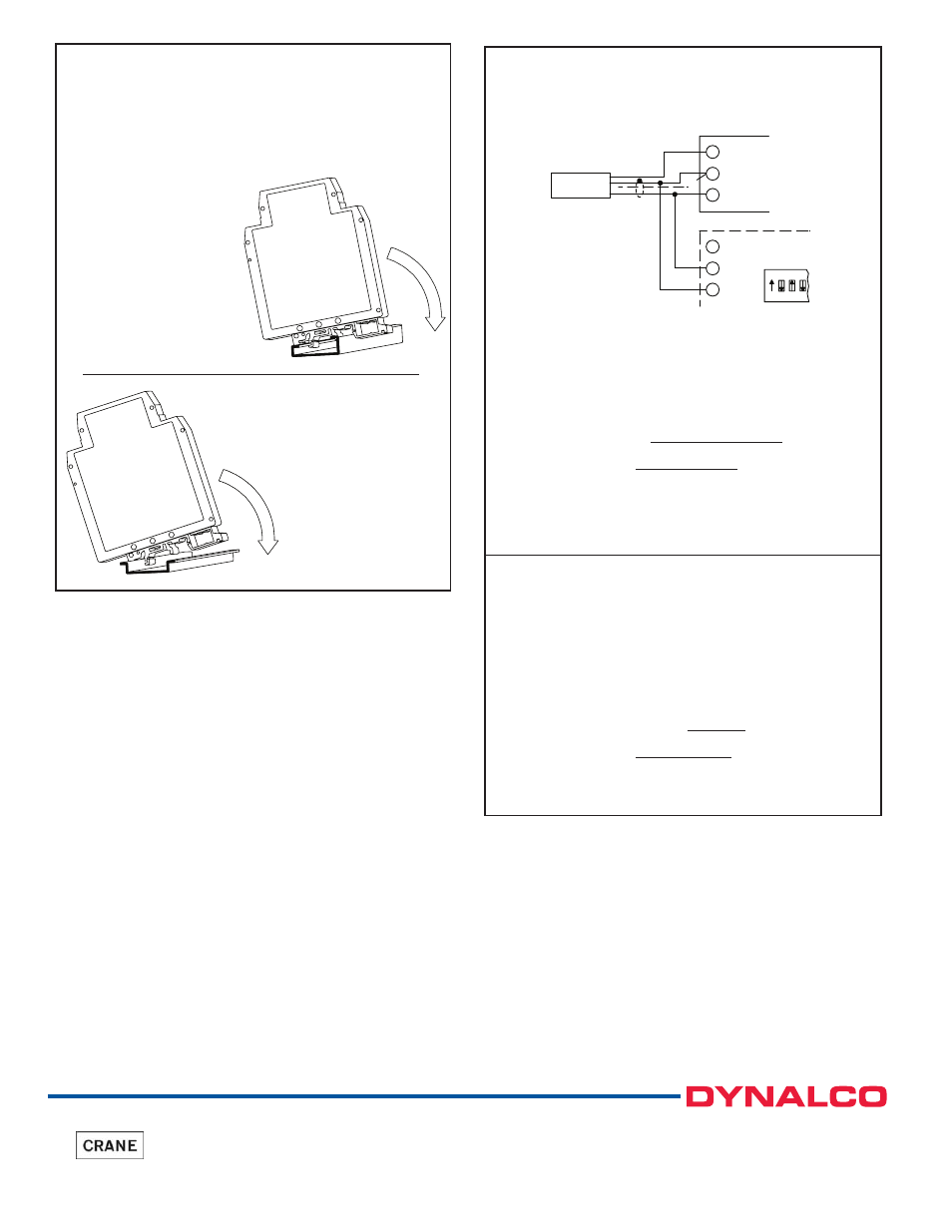
G Rail Installation
To install the SW-100 on a “G”
style DIN rail, angle the module
so that the upper groove of the
“foot” catches under the lip of the
top rail. Push the module toward
the rail until it snaps into place. To
remove a module from the rail,
push up on the bottom of the
module while pulling out away
from the rail.
T Rail Installation
To install the SW-100 on a
“T” style rail, angle the
module so that the top groove
of the “foot” is located over
the lip of the top rail. Push the
module toward the rail until it
snaps into place. To remove a
module from the rail, insert a
screwdriver into the slot on the
bottom of the “foot”, and pry
upwards on the module until it
releases from the rail.
APPLICATION 1
An APLR is connected to an LMPC (logic magnetic pickup) that is
sensing the speed of a 60 tooth gear attached to a shaft. The shaft speed
should not exceed 2000 RPM.
The SW-100 is placed in parallel with the APLR to activate an alarm
when an overspeed condition is detected, and to turn off the alarm when the
speed returns to normal. The Mode of Operation is set for Mode #1
(overspeed trip, automatic release upon return to normal).
To set the value of the alarm, either apply the maximum input signal as
described in Section 2.0 or determine the Trip Frequency using the
following formula:
Trip Freq. = units/measure x pulses/unit
seconds/measure
Trip Freq. = 2000 RPM x 60 PPR = 2000 Hz
60 sec
Set the Trip Frequency with the rotary switch for 2000 Hz.
With Trip point Offset set at 0.00% (No Offset) and Trip Point Hysteresis
set at 0.25%; activation of the relay occurs at 2000 Hz, and release occurs
at 1995 Hz.
APPLICATION 2
The SW-100 can be used in a speed monitoring system to detect when the
system drops below setpoint.
The SW-100 is wired to a PSAC (inductive proximity sensor) that is
sensing a key way on the shaft of a motor. The motor is turning at 1750 RPM.
When the speed of the motor drops below 1250 RPM, the SW-100 latches
the output until the user resets the output with an external push button.
The mode of operation of the SW-100 is set for 5 (UNDERSPEED
Latched trip, release only after Alarm Reset pulled to common). Determine
the Trip Frequency using the following formula:
Trip Freq. = RPM x PPR
60
Trip Freq. = 1250 RPM x 1 PPR = 20.83 Hz.
60 sec.
Set the Trip Frequency with the rotary switch for 20.83 Hz.
TROUBLESHOOTING
For further technical assistance, contact Dynalco at thenumber below.
Toll Free 800.368.6666 (US & Canada)
Main 954.739.4300 • Fax 954.484.3376 • www.dynalco.com
3690 NW 53rd Street, Ft. Lauderdale, FL 33309 USA
A division of Crane Co.
SNK
LOGIC
SRC
ON 1 2 3
7
8
9
+12V
INPUT
COMM.
COMM.
INPUT
+12V
8
9
7
APLR
LMPC
SW-100