4 calibration procedure, 1 required equipment, 2 connections – Dynalco DST-2000C Direction Sensing Tachometer User Manual
Page 9: 1 required, Equipment
DST-2000C Instruction Manual
9
2.3
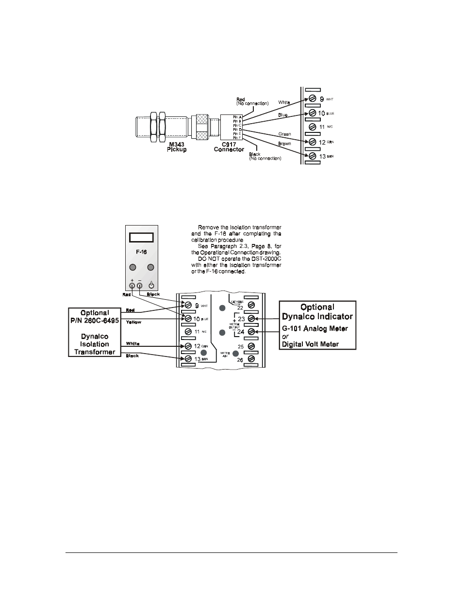
Wiring Connections Between DST-2000C & M343 Pickup Connector
Wiring connections between the DST-2000C and the M343 magnetic pickup
connector C917-X (X = length of connector cable in inches) are as follows:
2.4 Calibration
Procedure
The only calibration to the DST-2000C recommended by the factory is calibration of
the 0–1 mA Meter Output. {Note: The two potentiometers on the bottom of the PC
board are factory adjustments only and no user adjustment should attempted.}
2.4.1 Required
Equipment
•
Dynalco F-16 Frequency Generator or similar square wave generator
•
Dynalco G-101 meter or digital voltmeter
•
Dynalco isolation transformer p/n 260C-6495
2.4.2 Connections
•
Connect the G-101 to the meter output terminals of the DST-2000C: terminals
23 (+) and 24 (–).
•
Connect the F-16 signal generator to the DST-2000C terminals 9 (+) and 10
(–).
•
Connect the red lead of the 260C-6495 transformer to terminal 9 of the
DST-2000C and the yellow lead to terminal 10.
•
Connect the white lead of the 260C-6495 transformer to terminal 12 and the
black lead to terminal 13 of the DST-2000C.