B. c. a, B1. b2, Control panel – Drucker Diagnostics Model 642E Centrifuge User Manual
Page 5: Tube holder configurations
To verify the preset time: NOTE: Your centrifuge must be plugged in.
a. Push the OPEN / STOP button to disengage the lock and then
open the lid.
b. Push and hold the START button for approximately three (3) seconds. The Yellow
LATCHED indicator light will begin to flash, indicating program mode.
c. When you release the START button, the RUNNING indicator light will begin to
flash. Each flash represents one minute of run time.
d. Press the START button to verify the brake setting. When you release the START
button, the RUNNING indicator light will begin to flash. Each flash represents the
brake setting, from 1 to 10.
To change the preset time: NOTE: Your centrifuge must be plugged in.
a. Push the OPEN / STOP button to disengage the lock and then
open the lid.
b. Push and hold the START and OPEN buttons for approximately three (3)
seconds. The yellow LATCHED indicator light will begin to flash slowly, indicating
that you can now program run time.
03-0-0003-0068 642E Drucker
Revision: A
Tooling: LT-026
Material: 0.010” Polycarbonate
Finish: Velvet
Embossing Height: 0.010"
Adhesive: 3M 9502 or Permanent Equiv.
200 Shadylane, Philipsburg, PA 16866
(814) 342-6205 Fax: (814) 342-6211
www.druckerco.com
Black
White
Pantone 288 C
Model 642E Centrifuge
(Continued)
12. Push the ‘OPEN / STOP’ button. The ‘RUNNING’ indicator light should
go out and the motor should slow to a stop.
13. The lid should remain locked until the rotor has nearly stopped. If
the machine unlocks prematurely, contact The Drucker Company for
assistance.
Once the rotor has stopped, the interlock system will become
disengaged for sixty (60) seconds. The ‘UNLOCKED’ indicator light will
illuminate during this time.
14. To gain entry into the centrifuge after this period has ended, simply press
the ‘OPEN / STOP’ button. The lid will unlock for fifteen (15) additional
seconds.
After the centrifuge has passed this procedure it is ready for operation.
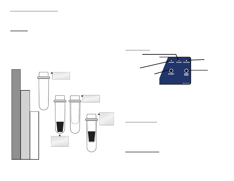
Control Panel:
Page 5
‘START’
Button
‘OPEN /
STOP’
Button
‘RUNNING’
Indicator
Light
‘LATCHED’
Indicator Light
‘UNLOCKED’
Indicator
Light
‘RUNNING’ Lights up when the machine
is in operation, (power is
being applied to the motor).
‘LATCHED’ Lights up when the lid has
been closed and latched
properly.
‘UNLOCKED’ Lights up to indicate that the
locking mechanism has been
deactivated, allowing access
to the rotor chamber.
‘START’
Begins a new run, (the lid
must be closed, see pg. 6).
‘OPEN / STOP’Allows for access into the
rotor chamber by disengaging
the locking mechanism. Entry
is only permitted when the
rotor is stopped. Pressing this
button during operation will
terminate the run and unlock
the lid after the rotor has
come to a stop.
Page 8
Tube Holder Configurations:
The Model 642E is capable of spinning test tubes up to 17 mm x 100 mm with
its horizontal rotor. Use the following chart and drawing to determine which tube
holder and cushion combination should be used with your application.
DIRECTIONS:
1. Compare the tube to be spun with the three boxes shown below.
2. Find the box that most closely matches the tube’s length. NOTE: The
tube length with its stopper or cap must be shorter then the chosen
box or the tube will not fit properly in the tube holder.
3. Match the letter from the chosen box with one of the configurations shown.
B.
C.
A.
* This part is available as an accessory. Contact The Drucker Company for assistance.
For Example: A tube is found to be as long as box B. Accordingly, we
can use a 100 mm tube holder with a 1525 cushion or a 75 mm tube
holder with no cushion, (configurations B1 or B2).
(cont.)
A.
RED
C.
GREEN
RED
GREEN
100 mm
Tube Holder
100 mm Tube
Holder with
1525 cushion*
75 mm
Tube Holder
75 mm Tube
Holder
with 1525
cushion*
B1.
B2.