Balanced loads – Drucker Diagnostics Model 614B Centrifuge User Manual
Page 4
Setup Location:
1. Unpack the centrifuge and verify that all of the supplied equipment is present.
2. Choose a setup location which meets the following criteria:
a) A bench top clearance height of 20” is required in order to open the lid.
b) The clearance envelope is the space around the centrifuge which is
required for safety. Choose a setup location which will allow for a
clearance envelope of at least 24” x 24”, (with the centrifuge at the center).
No person or hazardous material shall be permitted in the clearance
envelope during operation. The operator time within the envelope shall
be limited to the time necessary for loading, unloading and centrifuge
operation only.
c) Proper ventilation is necessary to prevent the overheating of samples as
well as premature failure of the centrifuge. Choose an area which will
allow unencumbered air flow.
d) The centrifuge is designed to secure to the operating surface by four
suction feet. No adjustment is necessary for leveling the centrifuge,
however, the surface should be flat and level.
e)
Be sure the outlet is always within reach as the line cord is the
means
of
emergency
disconnection!
Initial Setup Procedure:
If any problems are found during the initial setup procedure, refer
to the troubleshooting section on page 8. For further assistance,
contact The Drucker Company at
814-342-6205 or
814-692-7661
.
1. Plug the centrifuge in to an approved electrical outlet. For electrical safety,
the unit must always be properly grounded.
2. Turn the latch counter–clockwise and open the lid.
3. Spin the rotor by hand; check for free and level rotation.
4. Close the lid. Rotate the lid knob clockwise to its complete stop position.
5. Turn the centrifuge on by turning the timer to 10 minutes.
6. Listen to the centrifuge. A smooth whirring sound should be heard.
After the centrifuge has passed this procedure it is ready for operation.
Page 4
BALANCED LOADS
Your centrifuge must contain a balanced load in order to work properly.
Use the following rules when loading the rotor. Spinning balanced
loads will extend the life of the machine and produce better results.
1. Opposing tube holders must be identical and must contain the same
cushion, or none at all.
2. Opposing tube holders must be empty or loaded with equally
weighted
samples.
3. If an odd number of samples is to be spun, fill a tube with water to
match the weight of the unpaired sample and place it across from
this
sample.
Replacement Parts:
Part No.
Description
7724037
Foot, rubber
7751068
Switch, lid safety
7786047
Rotor, six–place fixed-angle
7735050
Motor, 1/30 H.P.
7722027
Timer, mechanical
7751043
Circuit Breaker
03-0-0003-0061 Front Panel Label
7760002
Power cord
7714101
Pawl, latch, lid
7714103
Knob, latch, lid
7712260
Lid
7724071
Hinge, friction
7732018
Seal, lid gasket
7732019
Seal, rotor chamber gasket
7713033
Tube holder, green, for 75mm tubes
7713031
Tube holder, red, for 100mm tubes
7713032
Tube holder, black, for 125mm tubes
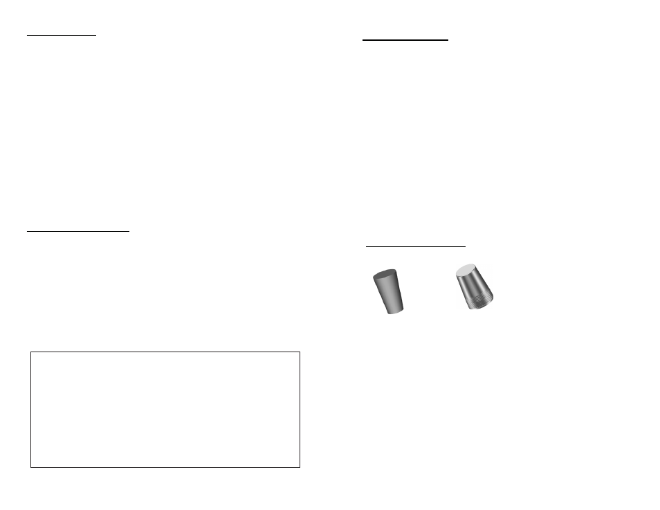
Available Accessories:
Shield
caps
p/n
7713011
1” Tube cushion
p/n 1525
Page 9