Cooper Instruments & Systems M5-1000 High Capacity Digital Force Gage User Manual
Page 18
CF
183
15
32-1113
REV
2
1010
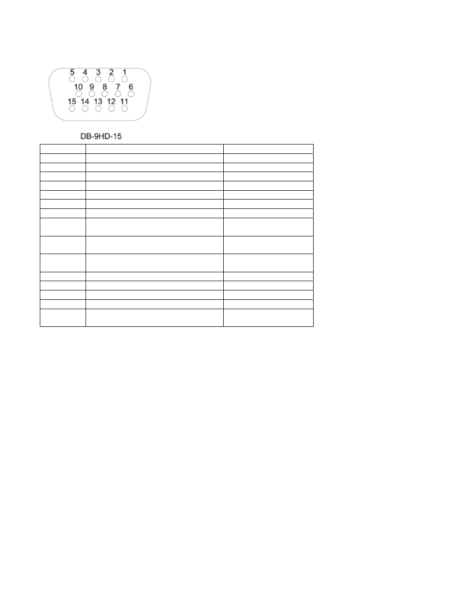
9.7 I/O Connector Pin Diagram (female)
Pin No.
Description
Input / Output
1
Signal Ground
---
2
Tension Overload
Output
3
RS-232 Receive
Input
4
RS-232 Transmit
Output
5
+12V DC
Output
6
Analog Output
Output
7
Compression Overload
Output
8
Mitutoyo Clock
Output Bit 2
Output
9
Mitutoyo Data
Output Bit 0
Output
10
Mitutoyo Request
Input Bit 3
Input
11
“Under” Set Point
Output
12
“Over” Set Point
Output
13
“Within” Set Point
Output
14 External
Trigger
Input
15 Mitutoyo
Ready
Output Bit 1
Output
9.8 Command Set / Gauge Control Language 2 (GCL2)
Series 5 force gauges may be controlled by an external device through the RS-232 or USB channel. The
following is a list of supported commands and their explanations. All commands must be terminated with a
Carriage Return character or with a Carriage Return/Line Feed combination. The gauge responses are always
terminated with a Carriage Return/Line Feed.
Request Readings
?
Request the displayed reading (dependant on operating mode)
?C
Request the current (real time) reading
?PT
Request the peak tension reading
?PC
Request the peak compression reading
?ET
Request the reading obtained during the External trigger mode
?A
Request the average reading obtained during the Average mode
18
Units
LB
Switch units to pound-force
OZ
Switch units to ounce-force
KG
Switch units to kilogram-force
G
Switch units to gram-force
N
Switch units to Newtons
MN
Switch units to Milli-Newtons
KN
Switch units to Kilo-Newtons
Basic Functions
CUR
Current mode (real time mode) for primary reading
PT
Peak Tension mode for primary reading