Baseline Systems Ethernet Radio User Manual
Page 5
BL-ER-P Ethernet Radio Unit for Pedestal
Installation Guide
1-866-294-5847
Rev 8.19.2014
www.baselinesystems.com
8. Attach the Ethernet cable to the Ethernet port on the Ethernet radio unit.
9. With the antenna and Ethernet cables pointing up, align the three mounting holes on the
Ethernet radio unit with the standoffs on the back wall of the pedestal. Use the screws
provided to secure the unit to the enclosure.
10. Plug the 5-pin connector from the Ethernet radio power cord into the upper 5-pin terminal
block on the right end of the controller board.
Note: If another connector is attached to the upper 5-pin terminal block, disconnect it
and then reconnect it to the lower 5-pin terminal block.
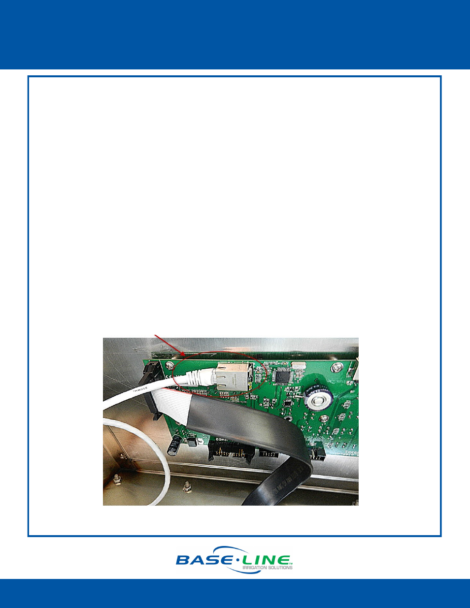
11. Plug the other end of the Ethernet cable into the Ethernet jack on the back of the display
board.
12. Reconnect the orange power connector to the board in order to the restore power to the
controller.
13. Replace the pedestal door, and then restart the controller.
BaseStation 1000: Press the RUN button.
BaseStation 3200: Turn the dial to the RUN position.
Page 5
Ethernet cable from the radio unit plugged into
the Ethernet port on the display board