Baseline Systems BaseStation 1000 User Manual
Page 7
Baseline Cell Modem Installation and User Guide
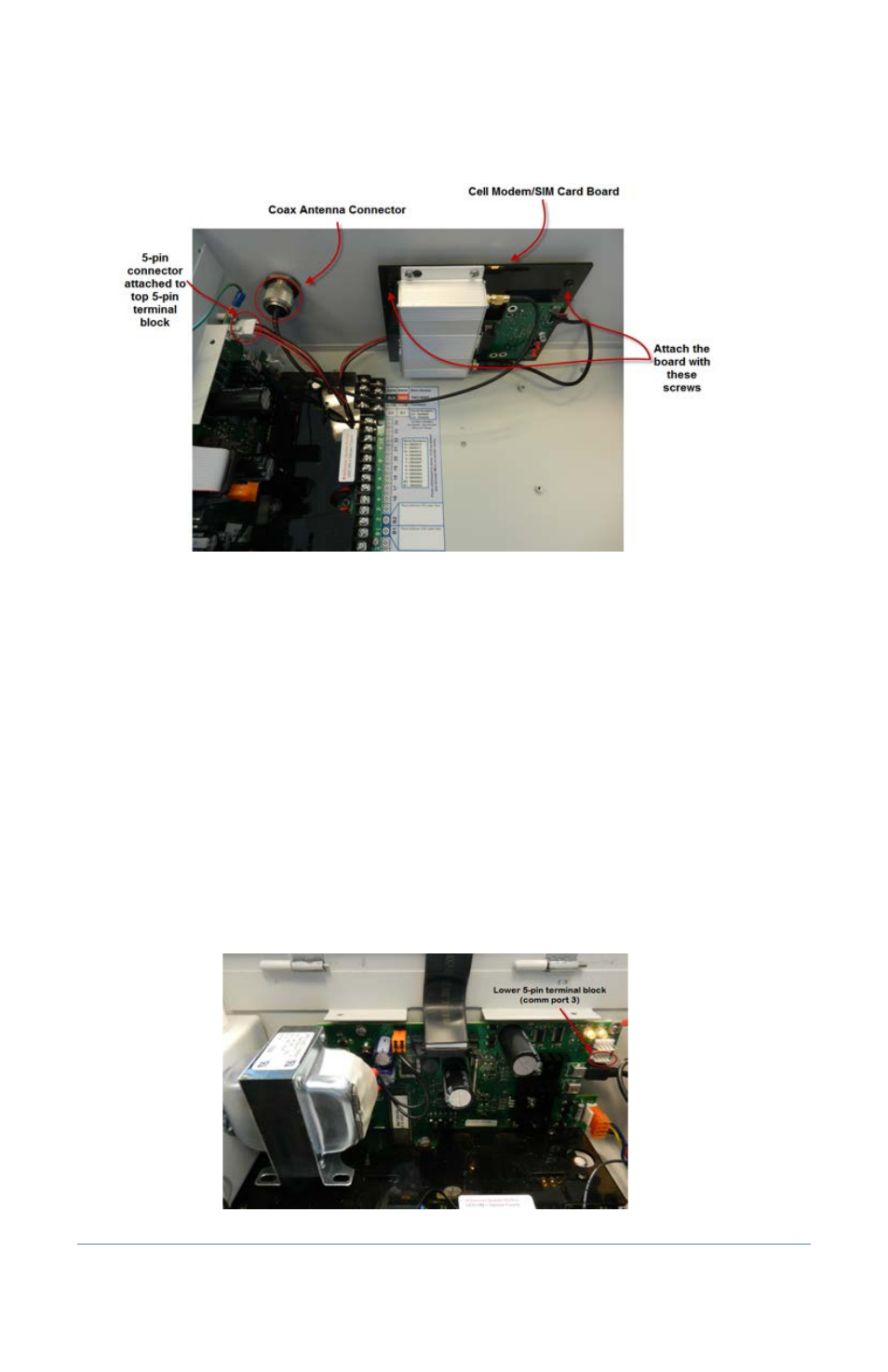
11. Align the holes on the cell modem/SIM card board with the mounting pins on inside roof of
the enclosure and use the screws provided to secure the board to the enclosure.
12. Perform one of the following options depending on your controller and firmware version:
Note: If another connector is attached to the 5-pin terminal block that you need, disconnect
it, and then reconnect it to the other 5-pin terminal block.
BaseStation 1000, firmware versions 1.4 and higher
Plug the 5-pin connector from the cell modem/SIM card board into the top 5-pin
terminal block (comm port 2) on right end of the controller board.
BaseStation 3200, firmware versions 12.4 – 12.7
Plug the 5-pin connector from the cell modem/SIM card board into the top 5-pin
terminal block (comm port 2) on right end of the controller board.
BaseStation 3200, firmware versions 12.8 and higher
Plug the 5-pin connector from the cell modem/SIM card board into the lower 5-pin
terminal block (comm port 3) on right end of the controller board.
Page 3