Nmea 0183 device connection – B&G Zeus2 12 User Manual
Page 18
12 |
Wiring |
Zeus2 Installation Manual
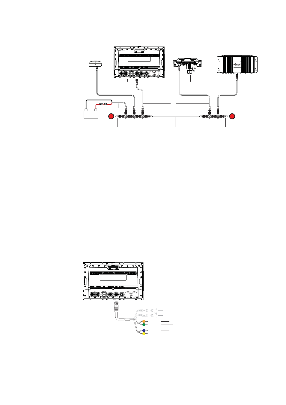
The following drawing demonstrates a typical small network. The backbone is made up of
direcly interconnected T-piece joiners and an extension cable, which is terminated at each
end.
+
_
12 V DC
T
T
9
8
5
7
6
4
3
2
1
9
1
GPS antenna
2
Zeus2
3
Broadband radar interface
4
SonicHub
5
‘Drop’ cables (should not exceed 6m (20’) each)
6
Power cable
7
Micro-C T junctions
8
Backbone
9
Micro-C terminator (one male, one female)
NMEA 0183 device connection
The Zeus2 display has an NMEA 0183 serial port, providing both an input and an output.
The port uses the NMEA 0183 (serial balanced) standard, and can be confi gured in the
software for diff erent baud rates up to 38,400 baud.
1
NMEA 0183 RX_B (orange)
2
NMEA 0183 RX_A (green)
3
NMEA 0183 TX_B (blue)
4
NMEA 0183 TX_A (yellow)
Note:
The connector for NMEA 0183 is labelled VIDEO, as the cable is dual purpose and carries
both composite video and NMEA 0183 (on seperate wires).
Talkers and Listeners
Do not connect multiple devices outputing data (Talkers) on to the serial input (Rx) of the
unit. The NMEA 0183/RS422 standard is not intended for this type of connection, and data
will be corrupted if multiple devices transmit simultaneously. The output however may drive
A
B
+
+
-
-
RX_B
RX_A
TX_B
TX_A
1
2
3
4