User responsibility, Installation guide, Warning – Amico Alert-3 LCD Alarm User Manual
Page 9: Caution, Danger
www.amico.com
9
STEP 6: SYSTEM POWER SUPPLY
TURN OFF POWER SWITCH before changing any modules and/or disconnecting any cables. Failure to do
so can cause the fuse to blow, damaging the circuitry.
i. Ensure that the ON/OFF switch is in the OFF position.
ii. Through the top left side of the back box, bring in the AC power wires. Knockouts are provided for making
conduit connections to the box. All wiring is to be installed according to local and national codes.
iii. Connect the AC power to the terminal blocks as shown in the wiring diagram (see Appendix B).
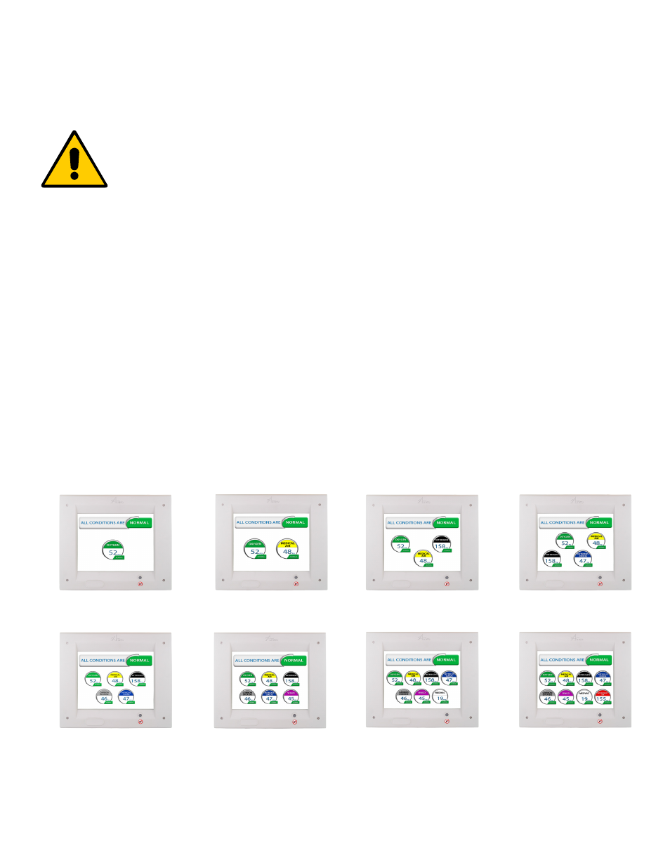
STEP 7: SENSOR MODULE
A: Gas Display (on screen location)
The location of gases displayed on screen is dependant upon which sensor channel each individual gas is connected
to. The display below indicates which sensor channel corresponds to each location the gas will be displayed on the LCD
screen.
A m i c o M i c r o p r o c e s s o r B a s e d A l a r m
P a g e : 4
USER RESPONSIBILITY
The information contained in this Installation and Operation Maintenance
Manual, pertains only to the ALERT-2 microprocessor based digital alarm.
This product will perform to conformity with the descriptions contained in this
manual, when assembled, operated, maintained and serviced in accordance
with the installation instructions provided.
The alarm
must be checked periodically. Parts that are broken, missing,
worn, distorted or contaminated,
must be replaced immediately. Should such
repair or replacement become necessary, please contact Amico Corporation
or their distributors.
All alarms should not be repaired, or altered without prior written or verbal
approval of Amico Corporation or it’s distributors. Failure to comply will void
all warranty on the alarm.
Statements in this manual preceded by the words
WARNING
,
CAUTION
,
DANGER and
NOTE
are of special significance. Please read these sections
carefully.
WARNING:
denotes steps which can prevent injury.
CAUTION:
denotes steps which can prevent damage to equipment.
DANGER:
denotes steps which can prevent electrical shock to equipment
or to prevent serious injury and/or death.
1
1
2
1
2
3
1
2
3
4
1
2
3
4
5
1
2
3
4
5
6
1 2 3 4
5 6 7
1 2 3 4
5 6 7 8
Installation Guide