Installation guide – Amico Alert-3 LCD Alarm User Manual
Page 10
10
Amico Pipeline
STEP 7: SENSOR MODULE
B: LOCAL (inside the back box)
i. The sensor module is provided with a 6”-8” [0.1 m - 0.2 m] twisted pair of wires.
One wire is red (positive) and the other wire is black (negative). Connect the wires
to the display module as shown in Appendix D. Take the red wire from the sensor
and attach it to terminal “Sensor +” on the display module. Take the black wire
from the sensor and attach it to terminal “Sensor -”. The terminal block on the
display module is clearly marked for proper connection of the sensor wires.
ii. Repeat the above procedures with the remaining sensor modules.
C: REMOTE (outside the back box)
i. The sensor module is provided with a 6” - 8” [0.1m - 0.2m] twisted pair of wires.
Connect the wires to a junction box (not supplied) located near the sensor as per
the wiring diagram.
ii. Connect a shielded twisted pair cable from the junction box to the back box
assembly. Knockouts are provided throughout the alarm back box. Up to 100 feet
[30.5 m] of 22 Gauge, shielded twisted pair cable should be used.
iii. Connect the red wire from the cable to the terminal on the display module
marked ”Sensor +”. Connect the black wire to terminal “Sensor -” as shown in the
wiring diagram (see Appendix E).
iv. Repeat the above procedures with the remaining sensor modules using the wiring
diagram.
NOTE: When remote sensors are used, a shielded or twisted pair cable is required
(BELDEN #8451 or equivalent, supplied by others).
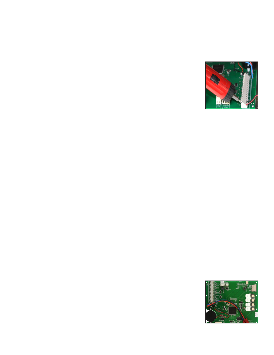
STEP 8: LCD DISPLAY MODULE
If the dry contacts for a generic alarm is to be used for remote monitoring, connect the wires
to the appropriate terminals: COM (Common), NO (Normally Open) or NC (Normally Closed),
using the diagram in Appendix A.
See Appendix G for contact rating.
Once the sensors are connected and the power has been turned on, use the following steps
to setup the LCD Alarm.
Installation Guide