Installation guide – Amico Alert-3 LCD Alarm User Manual
Page 7
www.amico.com
7
Installation Guide
STEP 1: THE ALARM BOX
Install the back-box to the studs of the wall at the desired height. Ensure that the box is securely in place. The mounting
brackets are adjustable to suit the thickness of the wall. MAKE SURE the box is parallel, squared and flush with the
finished wall surface to ensure that the frame assembly will fit properly.
STEP 2: FOR LOCAL SENSOR ONLY
If the sensors are to be mounted locally (inside the back box), the pipe stubs must be connected to the pipeline. Using
silver-brazing techniques, connect each pipe stub to its appropriate gas or vacuum while ensuring that the bottom of
the pipe stub is wrapped with a damp cloth. BE CAREFUL not to damage the DISS check-valve by overheating the lower
portion of the copper pipe. When the brazing of pipe stubs has been completed, the system can be pressure tested.
STEP 3: STANDING PRESSURE TEST
Perform a standing pressure test on the piping system as per NFPA-99 “Health Care Facilities.” Inspect all joints for leaks
and make certain each gas is piped to a correspondingly labeled gas service.
STEP 4: SENSOR
LOCAL (inside the back box)
i. Locate the gas-specific sensor module to be installed.
ii. In the back box, there are color coded gas labels located under the DISS Demand Check Valves. Each label
identifies where each sensor module is to be placed.
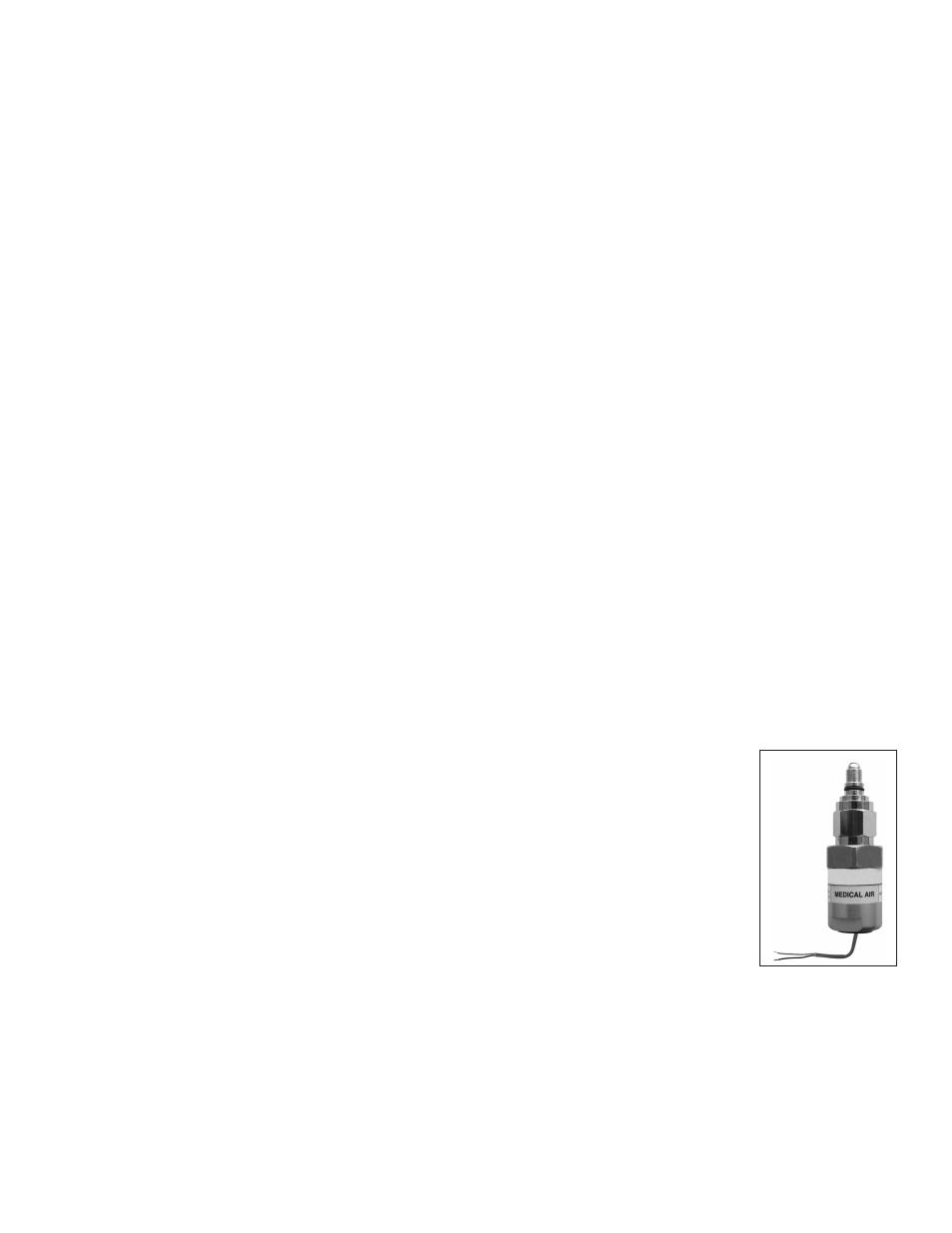
iii. The sensor module contains a gas-specific DISS fitting. Push the sensor module hex-nut
and nipple adapter up into the demand check-valve. With a wrench, tighten the nut so
that it makes a good seal.
Note: Pressure on sensors are not to exceed 250 psi for pressure sensors and 30 inHg for vacuum
sensors.
Alert-3 sensor operating pressure range:
Mid Pressure (0 to 99 psi)
-
Oxygen, Medical Air, Nitrous Oxide, Carbon Dioxide
High Pressure (0 to 249 psi) -
Nitrogen, Instrument Air
Vacuum
(0 to 30 inHg) -
Vacuum, WAGD, AGSS