Assembly and installation mira 45 floor stand, Head assembly, Cd e f – Amico Mira 45 User Manual
Page 8
8
Amico Lighting Solutions
Operating manual
(GB)
Page
17/40
7.
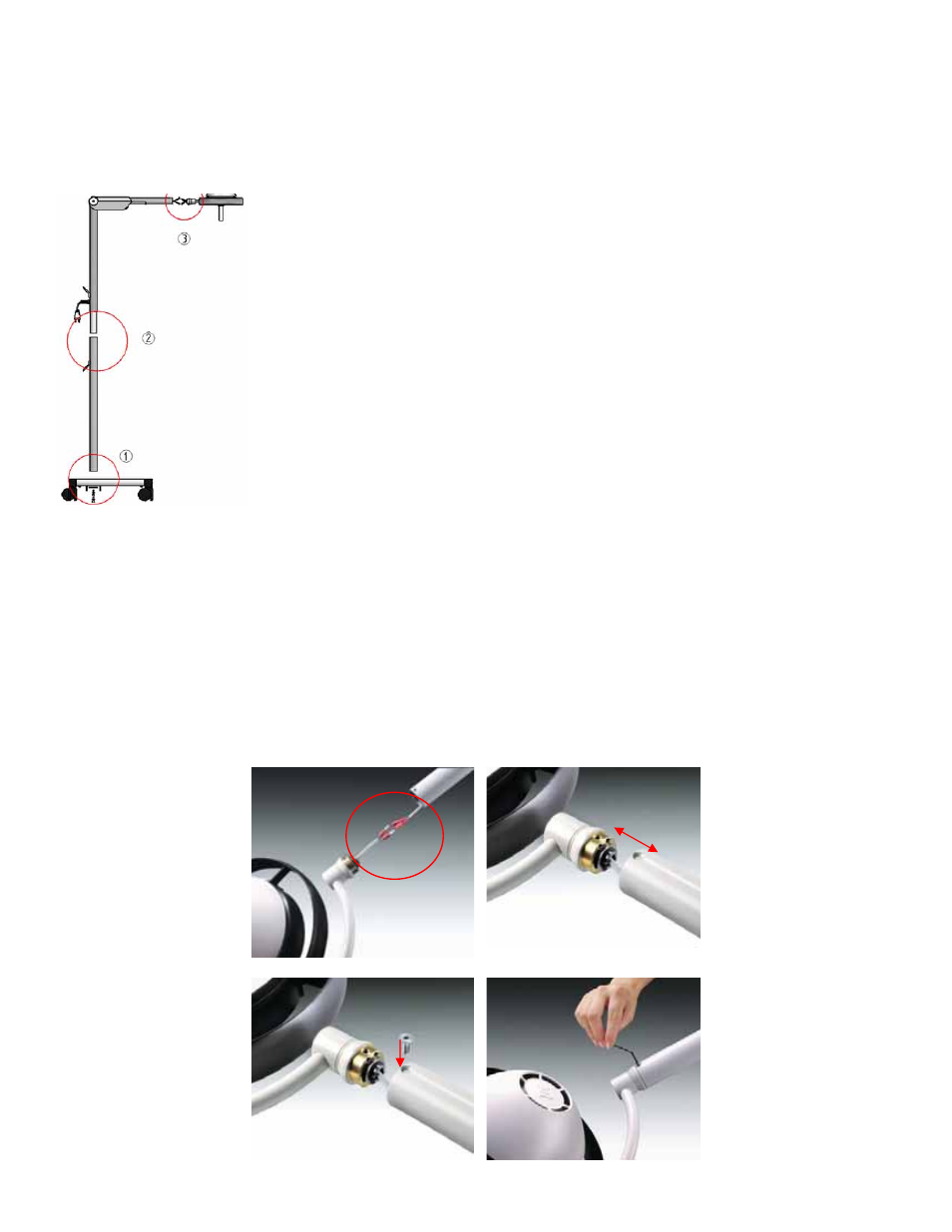
Assembly and Installation MIRA 45 Floor Stand
Mounting steps
c
Insert the support tube into the castor base and tighten the set-screws
(support disc, screws - 1xM8, 1 x M5 – and serrated washer).
d
Place the spring-loaded arm on the support tube and align the holes.
Attach the cable holder with the supplied screws and tighten.
e
Head Assembly (see below)
8. Head Assembly
Match the plug- and socket connectors as shown in Fig c completely. The
active parts has to be total covered. Align the hole on the end of the top arm
with the hole on the limiter and slide the limiter into the top arm (see Figs. d
and e). Insert and tighten the two set-screws to hold the head in place
(see Fig. f).
c
d
e
f
Operating manual
(GB)
Page
17/40
7.
Assembly and Installation MIRA 45 Floor Stand
Mounting steps
c
Insert the support tube into the castor base and tighten the set-screws
(support disc, screws - 1xM8, 1 x M5 – and serrated washer).
d
Place the spring-loaded arm on the support tube and align the holes.
Attach the cable holder with the supplied screws and tighten.
e
Head Assembly (see below)
8. Head Assembly
Match the plug- and socket connectors as shown in Fig c completely. The
active parts has to be total covered. Align the hole on the end of the top arm
with the hole on the limiter and slide the limiter into the top arm (see Figs. d
and e). Insert and tighten the two set-screws to hold the head in place
(see Fig. f).
c
d
e
f
1. Insert the support tube into the castor base and tighten the set-screws
(support disc, screws - 1 x M8, 1 x M5 – and serrated washer).
2. Place the spring-loaded arm on the support tube and align the holes.
Attach the cable holder with the supplied screws and tighten.
3. Head Assembly (see below)
Assembly and Installation MIRA 45 Floor Stand
Head Assembly
Match the plug- and socket connectors as shown in
Fig 1
completely. The active parts has to be total covered. Align the
hole on the end of the top arm with the hole on the limiter and slide the limiter into the top arm (see
Figs. 2 and 3
).
Insert and tighten the two set-screws to hold the head in place (see
Fig. 4
)