Assembly and installation mira 45 double ceiling – Amico Mira 45 User Manual
Page 6
6
Amico Lighting Solutions
Operating manual
(GB)
Page
15/40
5.
Assembly and Installation MIRA 45 Double Ceiling
Note: Only qualified technicians should carry out MIRA 45 installation.
Two people are required for assembling the MIRA 45 Double Ceiling. The
supply voltage must correlate with the voltage noted on the fixture’s rating
label. The ceiling fitting is to be used exclusively with ceilings that are either
solid, or supplied with a suitable high-strength ceiling-mounting solution.
c
Drill holes in accordance with the enclosed drilling template (∅=8mm;
depth=55mm). Clean out the drilled holes. Attach the anchor plate using
the four anchor bolts. Tap the anchor bolts completely in, using a hammer.
Tighten the nut with an open-ended wrench (approx. 3-4turns, 23Nm
torque.
Detailed view 1
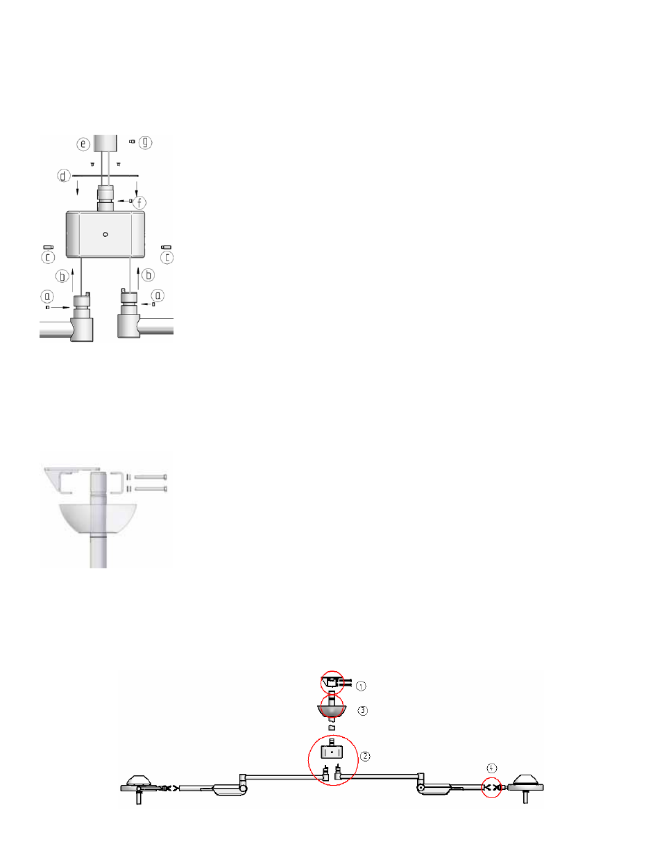
d
Perform this Step on a flat and level surface. Pull the cable through the
bearing head. Insert the slider into the groove of the arm joint, noting the
location of the fixing hole (1a). Align the hole in the slider with the set-
screw hole at the bottom of the bearing head. Insert the set-screw (18 mm)
into the hole to lock the slider in place (1c). Tighten the set-screw
completely, then loosen it by a maximum 1-quarter turn and check the
operation of the arm joint.
Check:
Set-screws had to be flush.
Pull the cable through the cover (1d) and the support tube (1e). Insert the
slider into the groove of the arm joint, noting the location of the fixing hole
(1f). Slide the support tube and the bearing head together (1e). Align the
hole in the slider with the set-screw hole at the bottom of the support tube.
Insert the set-screw (10 mm) into the hole to lock the slider in place (1g).
Tighten the set-screw completely, then loosen it by a maximum 1-quarter
turn and check the operation of the arm joint. Fix the cover (1d) with the
four screw (1h)
Check:
Set-screw has to be flush.
Detailed view 2
e
Place the O-ring and the ceiling cover over the support tube. Insert the
support tube into the anchor plate and fix it temporarily, using supplied
bolts (see detailed view 2). Align the support tube to the direction of the
fixture’s general usage. Tighten the screws on the anchor plate. Now
connect to the electrical power supply, as per the wiring diagram (see
sheet enclosed with the set of bolts). Slide the ceiling cover and the O-ring
upwards.
f
Head Assembly (see page 8)
Mounting steps
Operating manual
(GB)
Page
15/40
5.
Assembly and Installation MIRA 45 Double Ceiling
Note: Only qualified technicians should carry out MIRA 45 installation.
Two people are required for assembling the MIRA 45 Double Ceiling. The
supply voltage must correlate with the voltage noted on the fixture’s rating
label. The ceiling fitting is to be used exclusively with ceilings that are either
solid, or supplied with a suitable high-strength ceiling-mounting solution.
c
Drill holes in accordance with the enclosed drilling template (∅=8mm;
depth=55mm). Clean out the drilled holes. Attach the anchor plate using
the four anchor bolts. Tap the anchor bolts completely in, using a hammer.
Tighten the nut with an open-ended wrench (approx. 3-4turns, 23Nm
torque.
Detailed view 1
d
Perform this Step on a flat and level surface. Pull the cable through the
bearing head. Insert the slider into the groove of the arm joint, noting the
location of the fixing hole (1a). Align the hole in the slider with the set-
screw hole at the bottom of the bearing head. Insert the set-screw (18 mm)
into the hole to lock the slider in place (1c). Tighten the set-screw
completely, then loosen it by a maximum 1-quarter turn and check the
operation of the arm joint.
Check:
Set-screws had to be flush.
Pull the cable through the cover (1d) and the support tube (1e). Insert the
slider into the groove of the arm joint, noting the location of the fixing hole
(1f). Slide the support tube and the bearing head together (1e). Align the
hole in the slider with the set-screw hole at the bottom of the support tube.
Insert the set-screw (10 mm) into the hole to lock the slider in place (1g).
Tighten the set-screw completely, then loosen it by a maximum 1-quarter
turn and check the operation of the arm joint. Fix the cover (1d) with the
four screw (1h)
Check:
Set-screw has to be flush.
Detailed view 2
e
Place the O-ring and the ceiling cover over the support tube. Insert the
support tube into the anchor plate and fix it temporarily, using supplied
bolts (see detailed view 2). Align the support tube to the direction of the
fixture’s general usage. Tighten the screws on the anchor plate. Now
connect to the electrical power supply, as per the wiring diagram (see
sheet enclosed with the set of bolts). Slide the ceiling cover and the O-ring
upwards.
f
Head Assembly (see page 8)
Mounting steps
Note: Only qualified technicians should carry out MIRA 45 installation.
Two people are required for assembling the MIRA 45 Double Ceiling. The supply voltage
must correlate with the voltage noted on the fixture’s rating label. The ceiling fitting is to
be used exclusively with ceilings that are either solid, or supplied with a suitable high-
strength ceiling-mounting solution.
1. Drill holes in accordance with the enclosed drilling template (Ø=8 mm; depth=55
mm). Clean out the drilled holes. Attach the anchor plate using the four anchor bolts.
Tap the anchor bolts completely in, using a hammer. Tighten the nut with an open-
ended wrench (approx. 3-4 turns, 23Nm torque.
2. Perform this Step on a flat and level surface. Pull the cable through the bearing head.
Insert the slider into the groove of the arm joint, noting the location of the fixing hole
(1a). Align the hole in the slider with the set-screw hole at the bottom of the bearing
head. Insert the set-screw (18 mm) into the hole to lock the slider in place (1c).
Tighten the set-screw completely, then loosen it by a maximum 1-quarter turn and
check the operation of the arm joint. Check: Set-screws had to be flush. Pull the cable
through the cover (1d) and the support tube (1e). Insert the slider into the groove
of the arm joint, noting the location of the fixing hole (1f). Slide the support tube
and the bearing head together (1e). Align the hole in the slider with the set-screw
hole at the bottom of the support tube. Insert the set-screw (10 mm) into the hole
to lock the slider in place (1g). Tighten the set-screw completely, then loosen it by a
maximum 1-quarter turn and check the operation of the arm joint. Fix the cover (1d)
with the four screw (1h) Check: Set-screw has to be flush.
3. Place the O-ring and the ceiling cover over the support tube. Insert the support tube
into the anchor plate and fix it temporarily, using supplied bolts (see detailed view
2). Align the support tube to the direction of the fixture’s general usage. Tighten the
screws on the anchor plate. Now connect to the electrical power supply, as per the
wiring diagram (see sheet enclosed with the set of bolts). Slide the ceiling cover and
the O-ring upwards.
4. Head Assembly (see page 8)
Assembly and Installation MIRA 45 Double Ceiling