Great Plains 706NT Assembly Instructions User Manual
Page 4
151-120M
4/27/2005
Great Plains Mfg., Inc.
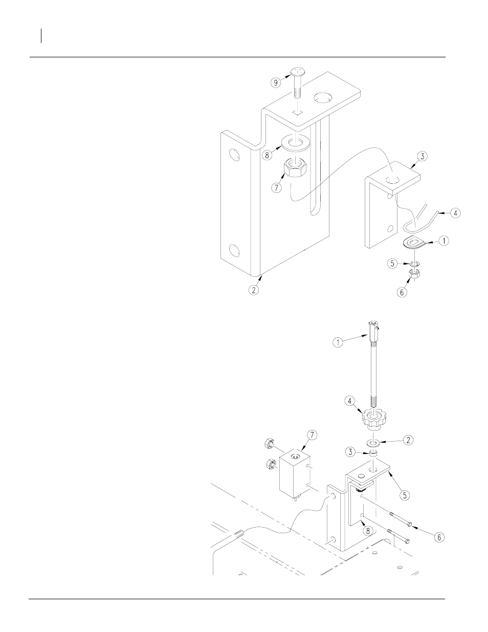
Hydraulic Valve Kit
4
Refer to Figure 6
8.
Replace bolt (9), new depth adjustment bracket
(3), washer (8), nut hex (7), tension spring re-
tainer (4), screw spring adjustment (1), washer
(5), and nut hex (6) on new depth stop valve
mount (2) provided in kit.
Refer to Figure 7
9.
Align knob (4), washer (2), and spacer tube
(3). Screw into top of mount (5) using screw
adjustment rod (1). Secure with flat washer
and nut hex.
10. Bolt new depth stop adjustment bracket (8)
to depth stop valve mount (5) and valve (7)
using bolts (6) removed in step 1.
Figure 6
23155
Figure 7
23149
See also other documents in the category Great Plains Gardening equipment:
- 1200 Parts Manual (210 pages)
- 706NT Material Rate (46 pages)
- 706NT Material Rate (50 pages)
- 2N-2410 Operator Manual (48 pages)
- 2N-2410 Operator Manual (56 pages)
- 12 Series Drills Assembly Instructions (6 pages)
- X-PresS 2006 Assembly Instructions (50 pages)
- TM500 Operator Manual (62 pages)
- 2010HDP Operator Manual (166 pages)
- YP1630F Material Rate (42 pages)
- YP2425 Operator Manual (162 pages)
- 3S-5000 Operator Manual (94 pages)
- 3PYP Operator Manual (188 pages)
- 3N-3010P Assembly Instructions (2 pages)
- 3N-3010 Assembly Instructions (9 pages)
- 3N-3010P Assembly Instructions (9 pages)
- PFH-15 Predelivery Manual (23 pages)
- PFH-15 Operator Manual (46 pages)
- PFH-15 Operator Manual (26 pages)
- P15126 Serial No 12724 (34 pages)
- DVN 8321 Operator Manual (38 pages)
- 3P500 Assembly Instructions (22 pages)
- 3P600 Assembly Instructions (12 pages)
- 605NT Assembly Instructions (8 pages)
- 605NT Assembly Instructions (4 pages)
- CPH-12 Assembly Instructions (3 pages)
- YP1625A-2420 24 Row 20-Inch Quick Start (6 pages)
- 8323 FCF Predelivery Manual (124 pages)
- P13937 (20 pages)
- 3323 DH Parts Manual (114 pages)
- YP3025-1820 25 Series 18 Row 20 Inch Quick Start (5 pages)
- CF500 Operator Manual (38 pages)
- PFH-15 Assembly Instructions (30 pages)
- 3500TM Parts Manual (106 pages)
- 1800TM Parts Manual (158 pages)
- YP2425A-2470 24 Row 70 cm Quick Start (5 pages)
- Simba Culti Press Operator Manual (38 pages)
- RU1999 Parts Manual (58 pages)
- 3N-30P Assembly Instructions (10 pages)
- 2510HDP Operator Manual (180 pages)
- YP1220 Parts Manual (136 pages)
- 3P500 Material Rate (68 pages)
- YP2425-3620 36 Row 20 Inch Quick Start (5 pages)
- 706NT Operator Manual (53 pages)
- 706NT Operator Manual (22 pages)