Plumbing operations – Great Plains 3P-FF900 Operator Manual User Manual
Page 24
3P-FF600, 3P-FF800 and 3P-FF900
500-643M
12/8/2009
22
Plumbing Operations
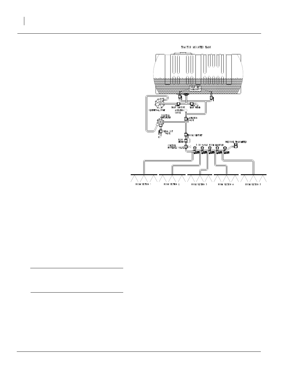
Refer to Figure 3
The basic plumbing diagram is shown for the
sprayer. A basic knowledge of how the sprayer is
plumbed will help you to understand how to oper-
ate your Great Plains Sprayer. Throughout this
manual, the components on this diagram will be
described with the terminology labeling these
components.
Fluid is drawn out of the sump in the tank and
passes through the pump. From the pump it pass-
es through the solution whirlfilter
®
and filters out
or grinds up all undissolved chemical and solid
particles. The fluid then passes through either the
Control Butterfly Valve or the Flow Meter.
The Control Butterfly Valve controls how much flu-
id goes to the boom. This is regulated by the
Raven SCS 450 or 440 controller. The fluid pass-
es through the Flow Meter and proceeds to the 3
or 5-Way Boom Manifold valves. If a Boom Valve
is on the fluid passes to its perspective Boom Sec-
tion and is sprayed out the individual nozzles.
The agitation can be set by adjusting the agitation
pressure valve while the pump is at operating
speed. Refer to Application Guide to adjust the
agitation.
To operate the hydraulic pump, first make sure
that the hydraulic hoses are routed correctly so
that the pump turns in the correct direction. See
the “Hydraulic Pump Hook-up on page 15, for
more details. To run the pump, push the hydraulic
lever in the “down” position. When you want to
stop the pump, push the hydraulic lever in the
“float” position.
IMPORTANT: Do not move the hydraulic lever
to the neutral position while the hydraulic
pump is running. To do so may cause damage
to the hydraulic pump.
Figure 3
Plumbing Diagrams Polyethylene Tank
22903