Hydraulic pump hook-up – Great Plains 3P-FF900 Operator Manual User Manual
Page 17
12/8/2009
500-643M
15
Preparation and Setup
Be certain that tractor lift capacity is adequate and that
tractor is weighted to maintain steering control. Failure to
do so may cause loss of vehicle control. Refer to tractor
specifications for tractor lift capacity and “Specifications
and Capacities,” page 42, for required lift capacity. Con-
sult the tractor’s operator’s manual for tractor weighting
recommendations.
1.
Determine the pin and spacer orientation needed
for the tractor, and securely fasten the hitch pins.
2.
Mount the 3-Point Sprayer to a tractor with the cor-
rect pin mountings determined from instruction
Step 1. Make sure that the sprayer frame is level so
that after the boom is assembled, it won’t hit the
tractor cab when the boom is folded or raised.
IMPORTANT: The category 4 narrow hitch (CAT IV-
N) spacers are not standard parts supplied with the
3-Point Sprayer.
Order 501-011S from a Great Plains dealer for the
Cat IV-N spacers.
NOTE: Be sure that the top 3-Point link is adjusted cor-
rectly so that the frame is level in operating position but
will not hit the cab in transport. The tractor 3-Point arms
should be adjusted to keep the sprayer level from side
to side with lift arm rigid.
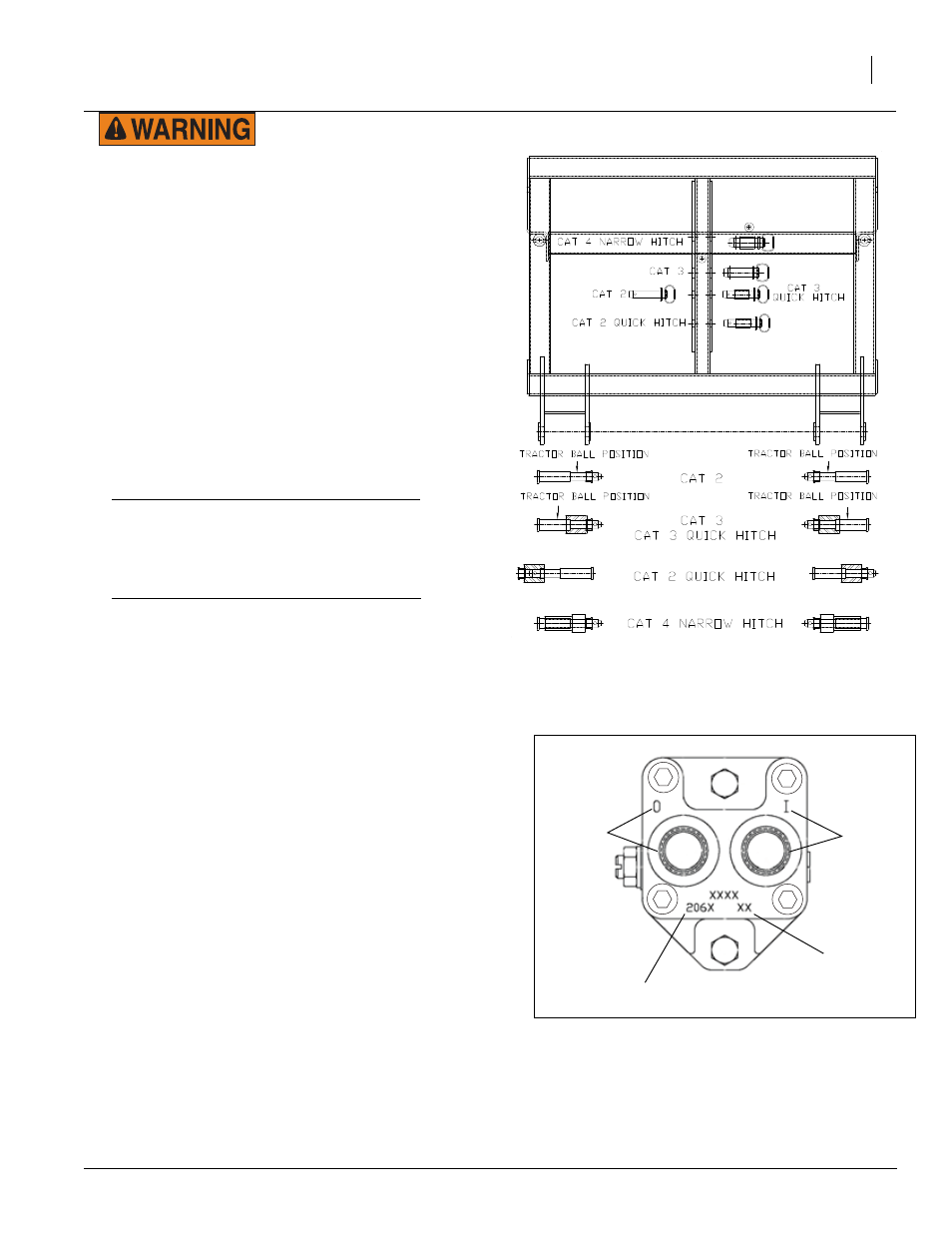
12654
Pin & Spacer Configuration
Hydraulic Pump Hook-Up
The hydraulic motor used on all liquid pumps is a 7 gpm
motor. If the tractor used on the sprayer does not have
the capabilities to adjust the remotes down to this flow,
then a hydraulic flow divider kit must be installed so that
flow can be controlled and to prevent operating the
pump at excessive speeds. See a Great Plains dealer.
To hook up the pump conduct the following instructions:
The pressure hose coming out of the tractor remotes
must be connected to the motor inlet port (“I” on current
pumps; “A” on older pumps, Base end on hose label),
and the return line connected to the motor outlet (“O”
on current pumps, “B” on older pumps, Rod end on
hose label). Before operating, place a stop in the neu-
tral position for the tractor hydraulics so that the hydrau-
lic lever can only be moved to the float and down
positions. Refer to the tractor’s operator manual or trac-
tor dealer on information for the neutral stop.
NOTE: Do not move the hydraulic lever into the neutral
position while the hydraulic pump is running. To do so
may cause damage to the hydraulic pump.
Figure 1
Ace Pump Connections
27141
Date Code
Motor Model (204N,206N,210N)
Inlet Port
Outlet Port