Great Plains 6548 Series VII Field Cultivator-Floating Hitch Operator Manual User Manual
Page 57
Great Plains Mfg., Inc.
Section 4: Operating and Maintenance
1/25/2005
Series VII 6330-6548 Field Cultivator, Floating Hitch 560-205M
55
10. Check safety chain hookup. Make sure all
warning lights are hooked up and functioning
correctly.
11. Check the tire pressure for proper inflation
and check the tightness of the lug bolts. Tire
pressure amounts are located on the sidewall
of each tire.
12. Check for any bolts that may need tightened
or retightened. Grease all the hinge points.
The hubs come pre greased and will not need
more grease at this time.
13. Put transport lock in place and refold the
machine slowly. Put wing stop pins in place.
Always use the transport pins when moving
from field to field. You are now ready to go to
the field.
General Operation Instructions and In-Field Adjustments
1. Remove the transport pins and unfold the
machine. Make sure the fold cylinders are fully
extended to allow the wings to fully flex in the
field.
2. If possible have someone observe the machine
during first time operation for levelness—front
to rear and wings to center frame. Adjust each
as needed. For front to rear, either extend or
shorten the length of the turnbuckle on the self-
leveling. Never run the machine with the back
lower (deeper) than the front. To adjust the
machine from side to side, use the eyebolt on
each wing. Adjust the inside wings first and
then the outside wings. The gauge wheels
should be set in field position to be ½” to 1 ½”
off the ground.
3. The ideal working speed is 6 to 7 mph.
Working too slow may cause plugging, poor
incorporation or mixing of crop residue and
reduced weed kill. Running too fast may
cause streaks in chemical incorporation and
ridging.
4. The field cultivator is designed as a secondary
tillage tool and is designed to leave a finished
seedbed following some form of fall or spring
tillage. For best results, if at all possible, run
the machine at a slight angle to the rows. This
will improve trash flow and help spread the
residue more evenly throughout the field.
5. When you have the machine set to the desired
working depth, set the depth stop slide on the
depth control bar. This is located at the front of
the machine on the brace bar. This will
maintain a constant depth each time after
raising and lowering the machine.
6. If after setting the depth stop, the detent on the
tractor kicks out before the stop contacts the
button on the depth stop, slow the hydraulic
flow speed down. If this problem still persists,
contact the factory service representative for
other possible adjustments. Do not try to
adjust the rebound valve without first
contacting the factory service rep.
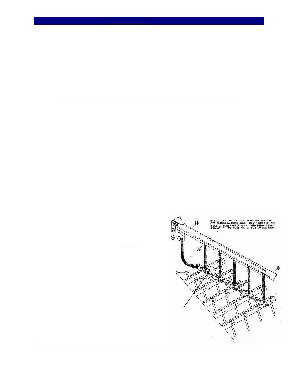
7. Adjust the drag to leave the desired results
while maintaining the trash flow through the
drag.
a.) On the spike drag, start with 5 links
hanging from the chain in drag arm bottom
slot. (This is the starting point for worst
conditions.) The cleaner the ground, the
shorter the pull chain may be pulled up.
On the spike drag, one of the links in the
first row of angles is turned over. This
allows the trash to start flowing through the
drag easier by changing the angle of the
ASSEMBLE WITH LINK UP AS
SHOWN. IN SOME
CONDITIONS THE FRONT
LINK MAY BE ASSEMBLED
DOWN TO HELP START
TRASH TO FLOW THROUGH
THE HARROW.
- 6546 Series VII Field Cultivator-Floating Hitch Operator Manual 6544 Series VII Field Cultivator-Floating Hitch Operator Manual 6541 Series VII Field Cultivator-Floating Hitch Operator Manual 6539 Series VII Field Cultivator-Floating Hitch Operator Manual 6537 Series VII Field Cultivator-Floating Hitch Operator Manual 6332 Series VII Field Cultivator-Floating Hitch Operator Manual 6330 Series VII Field Cultivator-Floating Hitch Operator Manual