Outside wing assembly – Great Plains 6548 Series VII Field Cultivator-Floating Hitch Operator Manual User Manual
Page 21
Great Plains Mfg., Inc.
Section 1: Assembly
1/22/2005
Series VII 6330-6548 Field Cultivator, Floating Hitch 560-205M
19
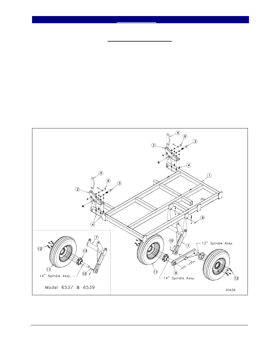
Outside Wing Assembly
On 5-section models, assemble the
outside wing (1) by attaching the outside hinges
(2) to the wing with 1 x 6 hex bolt (3) and 5/8 x
3 x 5 1/2 u-bolts (4) as shown in Figure 6. Use
a nylon lock nut on the 1 x 6 hex bolt (3) with
lock washers and hex nuts on the u-bolt.
Attach the 180 degree rocker (5), bulge side
out, with the 1 x 3 headed pin (6), 1” machine
washer and 3/16 x 2 cotter pin.
Attach the outside wheel bracket (7) just
as we did the inside ones, using the 11/4 x 6
pins (8) and 3/8 x 2 1/4 Gr.8 hex bolts & top
lock nuts. Slide the walking beam assembly (9)
into the wheel bracket sleeve as shown in
Figure 6. Again, it is recommended to use
some form of anti-seize product on the spindle.
Secure with 5/16 x 3 clevis pin (10) and 5/32 x
1 1/2 cotter pin. Note that the longer 14” long
spindle assembly goes to the front. Bolt on the
9.5L x 15 tire and wheels (11) with the 1/2 x 1
1/4 lug bolts (12).
Model 6537 & 6539 use one tire and a
14” Hub & Spindle assembly (13) as shown in
insert.
Figure 6
- 6546 Series VII Field Cultivator-Floating Hitch Operator Manual 6544 Series VII Field Cultivator-Floating Hitch Operator Manual 6541 Series VII Field Cultivator-Floating Hitch Operator Manual 6539 Series VII Field Cultivator-Floating Hitch Operator Manual 6537 Series VII Field Cultivator-Floating Hitch Operator Manual 6332 Series VII Field Cultivator-Floating Hitch Operator Manual 6330 Series VII Field Cultivator-Floating Hitch Operator Manual