Assembly instructions – Great Plains Auxiliary Down Pressure Spring User Manual
Page 2
198-962M
4/8/2004
Great Plains Mfg., Inc.
Auxiliary Down Pressure Spring
Assembly Option
2
Assembly Instructions
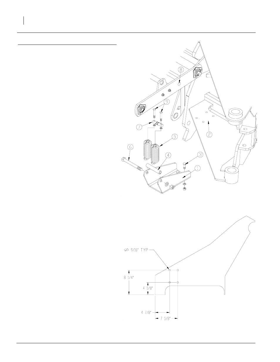
Refer to Figure 1
Note: Before performing this installation unfold
the drill on level ground. Raise the drill to the
transport position and install the transport locks.
Turn the tractor off and remove the key.
1.
Mount the down pressure spring anchor (1) to
the drill frame at the holes (2). Place the an-
chor (1) so the holes for the spacer tube are
facing towards the front of the drill. Use four
1/2" x 1 1/2" bolts, 1/2" lock washers and 1/2"
nuts. Tighten bolts to secure anchor.
Note: If your drill does not have holes it will be nec-
essary to drill them. Use dimensions in figure 2 for
location.
2.
Insert the spacer tube (4) through the loop
ends of two of the spring assemblies (5). Align
the spacer tube (4) between the two holes in
the spring anchor (1) and secure it in place
with a 3/4" x 7" bolt (6), 3/4" lock washer and
3/4" nut. Tighten bolt.
3.
Locate the hole marked (8) in the contact
wheel mounting arm. (This hole will be direct-
ly above the spacer tube holding the springs).
Insert the down pressure spring rod (7) in
hole (8) and hold it in place with a 1" external
snap ring on each side of the arm.
4.
Insert a 1/2" x 4" bolt (9) in each of the two
holes located in the spring rod (7). Thread a
1/2" jam nut on each bolt then thread the bolts
in to the tops of the springs (5).
5.
Adjust the tension on the springs by screwing
the bolts (9) down. Adjust to be 1/2" less ten-
sion than on original springs. Be sure to ad-
just the bolts evenly. This can be checked by
measuring the distance between the top of
the springs (5) and the top of the bolts (9). Do
not adjust top bolt any closer than 1" to avoid
premature bearing failure. When the desired
tension has been set, lock bolts (9) in place
with the 1/2" jam nuts.
6.
Repeat above steps to install down pressure
springs on the other contact wheel.
Refer to Figure 2
For drills without holes use the measurements in
figure 2. Figure 2 shows measurements for the
left-hand side of the drill, mirror the measure-
ments to drill holes on the right-hand side of the
drill.
Figure 1
Installation
Figure 2
Dimensions
20178
20177