Great Plains CF600 Predelivery Manual User Manual
Page 9
7
Section 1 Assembly
2/2/06
CF500 and CF600 Hydraulic Cross-Fold Boom 506-582Q
Great Plains Mfg., Inc.
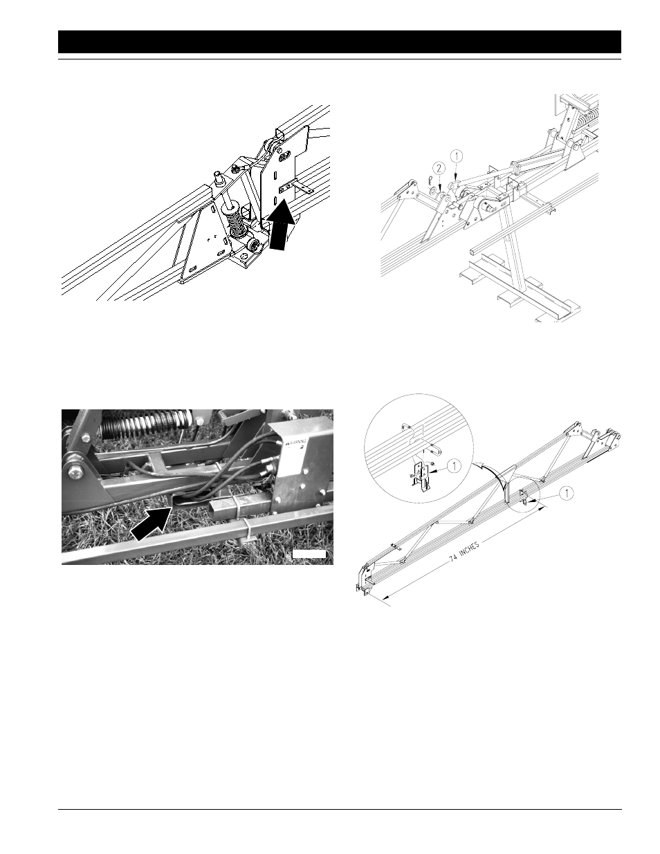
5.
Check both wings to see that jumper-nozzle brackets
face to the rear. If necessary, remove bracket from
front of wing and mount on rear of wing.
Figure 1-11
Jumper Nozzle Bracket to Rear
6.
If customer purchased an electric-hydraulic control,
install the optional control at this time. Refer to Elec-
tric-Hydraulic Control Installation Instructions, part
number 506-605M.
7.
Plumb hydraulic hoses. Route hydraulic hoses
through lift brackets to tractor. See Figure 1-12.
Figure 1-12
Route Hydraulic Hoses to Tractor
8.
Place a block under fold cylinders so cylinder rods will
not hit anything when extended.
9.
Cycle cylinders in and out several times to remove air
from system.
16911
17609
10. Refer to Figure 1-13. Pin cylinder rods (1) to clevis (2)
on inner-arm sections.
Figure 1-13
Install Hydraulics
11. Using 5/16-inch u-bolts and flange nuts, mount fold
brackets (1) on inner-arm sections. See Figure 1-14
for specific location.
Figure 1-14
Install Fold Brackets
16915
16900