Great Plains CF600 Predelivery Manual User Manual
Page 15
13
Section 2 Preparation and Setup
2/2/06
CF500 and CF600 Hydraulic Cross-Fold Boom 506-582Q
Great Plains Mfg., Inc.
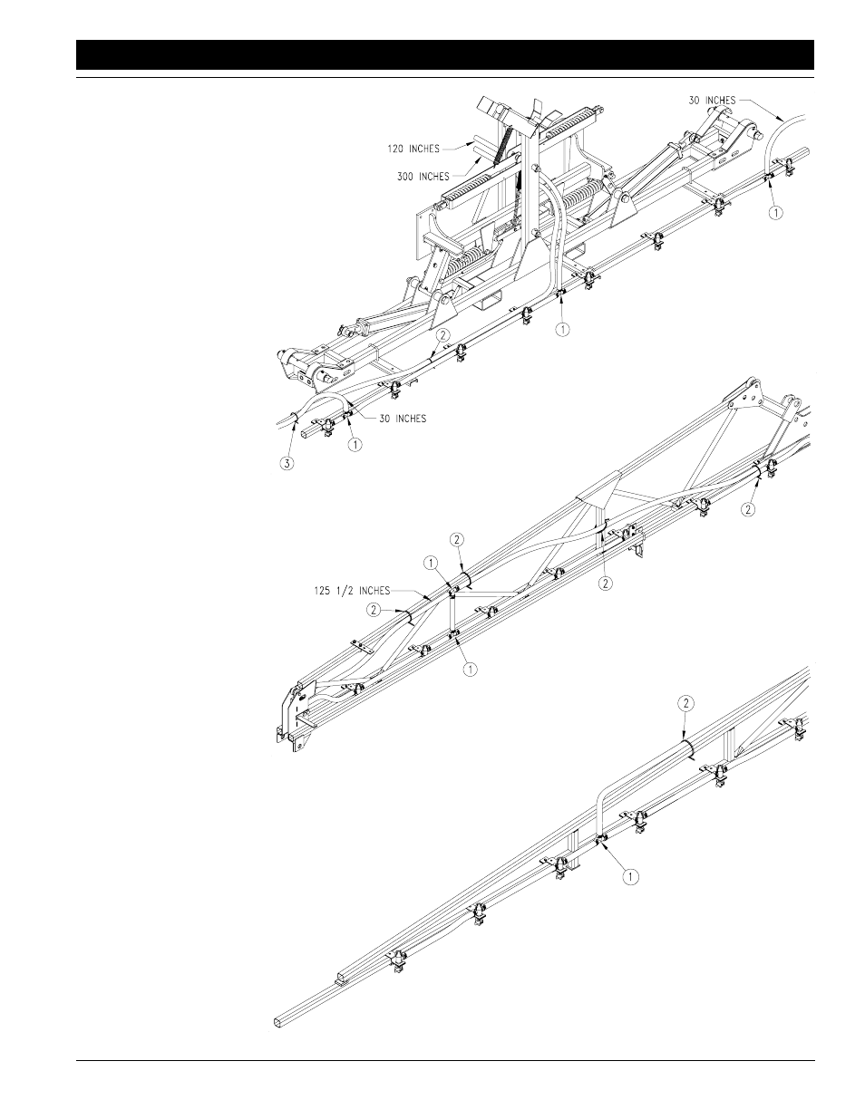
Figure 2-14
Dry Boom Nozzles, Center Section
Figure 2-15
Dry Boom Nozzles, Inner Arm
Figure 2-16
Dry Boom Nozzles, Outer Arm
16940
16996
16995
The illustrations on this
page are an example of
where to place end noz-
zles, tee-nozzles and tee-
fittings. Placement will de-
pend on nozzle spacing.
When mounting nozzles
on the left-hand, inner arm,
mount nozzles on the in-
side of the arm as shown in
Figure 2-15. Mount all oth-
er nozzles to the rear.
4.
Plumb nozzles. From the
roll of 3/4-inch hose, cut
lengths to connect noz-
zles. Use worm clamps to
secure hoses to nozzles.
The illustrations on this
page are an example of
where to place tee-fittings
(1) for supply lines. Your
goal is to have a tee-fitting
for each wing and center
section so each boom sec-
tion can have its own sup-
ply line. Use zip ties (2) to
secure hoses.