Great Plains CF600 Predelivery Manual User Manual
Page 14
12
Section 2 Preparation and Setup
CF500 and CF600 Hydraulic Cross-Fold Boom 506-582Q
2/2/06
Great Plains Mfg., Inc.
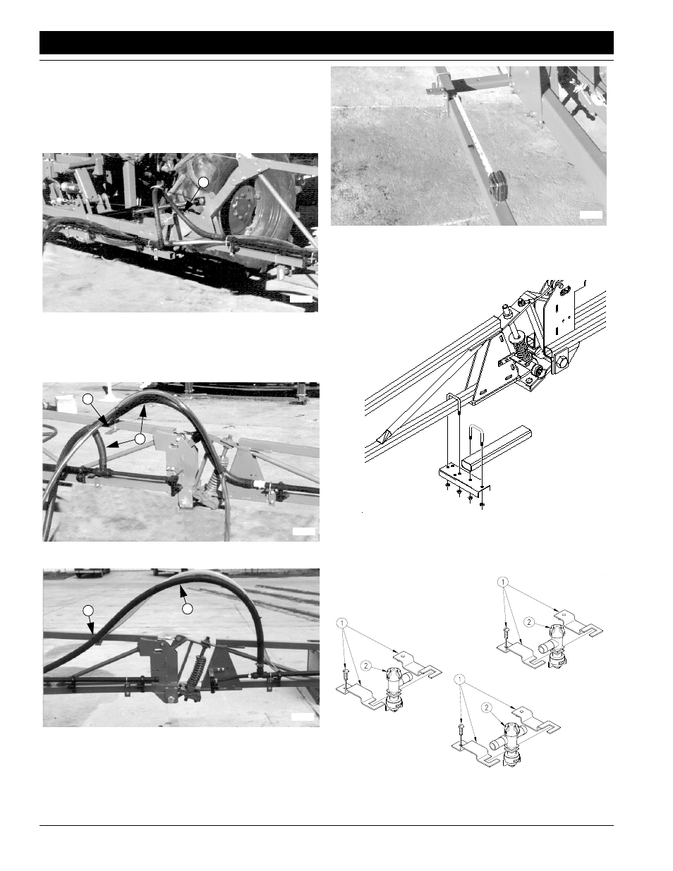
3.
Plumb wet boom.
For the following instructions, refer to Figure 2-6, page
10, or Figure 2-7, page 11, for an overview of hose
connections for entire boom.
Use pre-cut supply lines (1) to connect tubing as
shown in Figure 2-8, Figure 2-9 and Figure 2-10.
Figure 2-8
Center Section to Jumper Section
On wings, use cable ties to secure supply line to
bracket (2) on inner-arm section. See
Figure 2-9
Inner to Outer Arm, 20-Inch
Figure 2-10
Inner to Outer Arm, 30-Inch
Dry Boom Option
1.
Using a felt-tip marker, mark nozzle spacing on boom
to help identify nozzle locations. See Figure 2-11.
17018
1
17019
1
2
17263
1
2
Figure 2-11
Mark Tube for Nozzle Spacing
2.
Mount jumper-nozzle brackets on wing sections
where necessary. See Figure 2-12.
Figure 2-12
Mount Jumper-Nozzle Brackets
3.
Refer to Figure 2-13. Using mounting clamps (1),
mount nozzles (2) at marked locations.
Figure 2-13
Mount Nozzles
17013
17015
17077