Great Plains CF600 Predelivery Manual User Manual
Page 12
10
Section 2 Preparation and Setup
CF500 and CF600 Hydraulic Cross-Fold Boom 506-582Q
2/2/06
Great Plains Mfg., Inc.
If wet-boom has 30-inch nozzle spacing, move jump-
er-nozzle bracket from inner-arm section to outer-arm
section.
Figure 2-5
Bracket on Outer Arm for 30-Inch Spacing
For a starting reference point to help you mount tub-
ing, mark boom center point on nozzle tube. To find
center, measure mid point of center posts.
2.
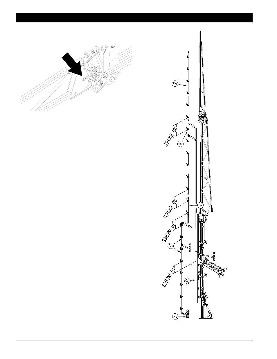
Mount wet-boom tubing.
Refer to Figure 2-6 or Figure 2-7, depending on noz-
zle spacing.
Start with yellow-tagged, center-section tubing. Of the
four tubing sections, set two jumper sections (1) aside
for later assembly. Assemble two remaining sections
(2) together. For 20-inch nozzle spacing, u-bolt center
tubing section (2) to nozzle tube (3) so middle nozzles
are 10 inches from center. For 30-inch nozzle spac-
ing, u-bolt center tubing section (2) to nozzle tube so
middle nozzle is at center. Mount jumper sections (1)
on left and right of center-section tubing. Use end
nozzles as a reference to mount jumpers at the cor-
rect nozzle spacing.
For each wing, distinguish tubing sections by identify-
ing jumper nozzle (4). Mount tubing on wings so jump-
er nozzle can be mounted on jumper-nozzle bracket.
Mount remaining tubing section (5) to other arm sec-
tion. Use end nozzles as reference to mount other
tubing section at the correct nozzle spacing.
17014
Figure 2-6
Wet Boom, 20-Inch Spacing
17258