Great Plains 4000TM Operator Manual User Manual
Page 23
Great Plains Manufacturing, Inc.
Preparation and Setup
19
12/03/2013
586-537M
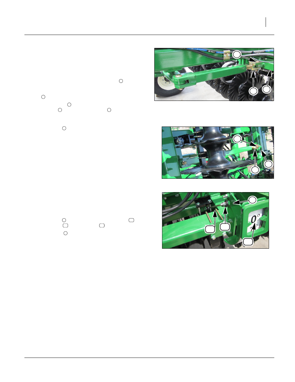
Refer to Figure 17 and Refer to Figure 18
Note: Note the two different turnbuckles used. One has a
rocker between two turnbuckles and the other has just
one turnbuckle between the front and rear gang bars.
They both adjust the same way.
24. When the front gang adjusting cylinders
Gang Angle Adjustment” on page 18, have been
adjusted and are in the full retract position the rear gang
bar
should be parallel to back frame tube.
25. If rear gang bar
is not parallel to back frame tube,
remove pin
from turnbuckle end
and shorten turn-
buckle end by turning clevis to bring gang bar closer and
lengthen clevis to get gang bar to retract all the way.
26. Re-install pin
when adjustment is made.
27. When the front and rear gangs are adjusted and gang
angle cylinders are fully retracted then the gang angle
indicator will need adjusted.
28. Remove bolt
from either end of gauge link
and turn
threaded end
until indicator
reads 0 degrees.
29. Re-install bolt
to secure gauge link.
Figure 17
Rear Gang Angle Rocker
42252
7
6
8
1
6
6
7
8
Figure 18
Rear Gang Angle Straight
42860
7
6
8
7
Figure 19
Gang Angle Indicator Adjustment
42253
10
11
12
9
9
10
11
12
9