Transport locks, Wing fold, Transport locks wing fold – Great Plains 4000TM Operator Manual User Manual
Page 20
16
3500-4000TM
Great Plains Manufacturing, Inc.
586-537M
12/03/2013
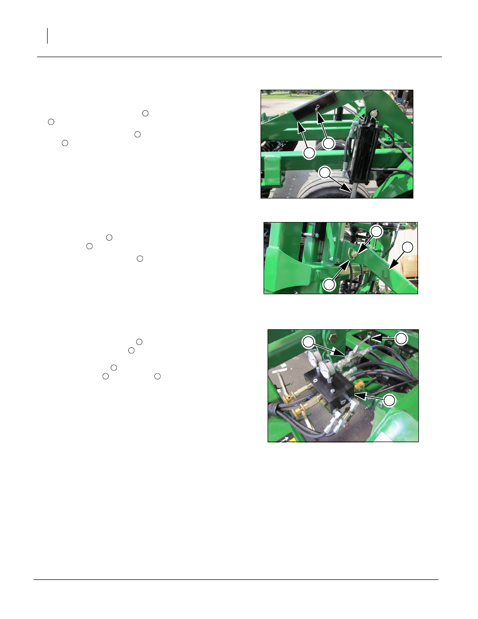
Transport Locks
Refer to Figure 8
4.
Once the cylinders are connected, raise the unit com-
pletly. If the transport locks
are in place on cylinders
, remove them at this time.
5.
Store the transport locks
in hole of the lift mechanism
link
.
Note: Always use transport locks and wing fold pins when
transporting.
Wing Fold
Refer to Figure 9
6.
If wing stop pins
are installed remove pins from wing
stop clevis
.
7.
Install pin in storage tube
on wing stop.
Note: The wing locking valve
is located on the bypass/
down pressure valve
to prevent wing movement dur-
ing transport and maintenance. The valve is shown
with the handle
in the open position. To close the
locking valve
, turn handle
90 degrees, to keep
wings from un-folding.
8.
Once the transport locks, wing stop pins are removed
and wing fold valve is in the open position (as shown),
unfold the wings.
Note: Make sure no one is under the wings during the un-
folding process. Watch for leaks and make sure hoses
do not get pinched during the initial unfolding process.
9.
Once the machine is unfolded, raise and lower the
machine several times to purge air from the lift system.
Again, watch for any leaks and tighten if necessary.
Figure 8
Transport Locks
42066
2
3
1
1
2
1
3
Figure 9
Wing Fold Pins
42249
1
2
3
1
2
3
Figure 10
Wing Lock Valve
43101
4
5
6
4
6
5
4
5