Manual gauge wheel, Hydraulic gauge wheel, Manual gauge wheel hydraulic gauge wheel – Great Plains 7336 DH Predelivery Manual User Manual
Page 21
Great Plains Manufacturing, Inc.
Assembly
17
2014-06-25
556-235Q
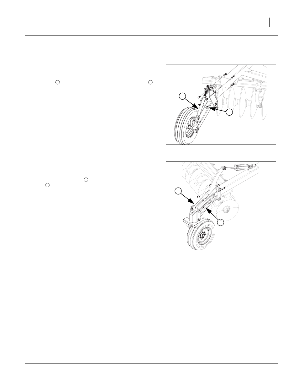
Manual Gauge Wheel
Note: If your machine is equiped with hydraulic gauge wheels then proceed to step 50.
Refer to Figure 16
47. When light brackets are installed, unfold the disk and watch
that everything clears the brackets. Install the gauge wheel
assembly
(if applicable) with the
3
⁄
4
” x 2” hex bolts
,
3
⁄
4
” lock washers and
3
⁄
4
” nuts to wing frame as shown.
48. Tighten all bolts to specs, See “Torque Values Chart” on
49. Once the gauge wheels are in place, the assembly of the
disk harrow is complete. At this time the unit should be
checked over for any loose bolts. Air pressure in the tires
should be checked, See “Tire Inflation & Warranty” on
page 20. Refer to the lubrication section of the “Operators
Manual” for the lubrications for this machine. If there is any
rear attachment, it should be installed at this time.
Hydraulic Gauge Wheel
Refer to Figure 17
50. When light brackets are installed, unfold the disk and watch
that everything clears the brackets. Install the hydraulic
gauge wheel assembly
(if applicable) with the
3
⁄
4
” x 2” hex
bolts
,
3
⁄
4
” lock washers and
3
⁄
4
” nuts to wing frame as
shown. Connect hydraulic cylinder to the gauge wheel arm
lever with pin provided.
51. Tighten all bolts to specs, See “Torque Values Chart” on
52. Once the gauge wheels are in place, the assembly of the
disk harrow is complete. At this time the unit should be
checked over for any loose bolts. Air pressure in the tires
should be checked, See “Tire Inflation & Warranty” on
page 20. Refer to the lubrication section of the “Operators
Manual” for the lubrications for this machine. If there is any
rear attachment, it should be installed at this time.
Figure 16
Manual Gauge Wheel
41515
1
2
1
2
4
3
Figure 17
Hydraulic Gauge Wheel
43463
3
4