Hitch and lever link assembly – Great Plains 7336 DH Predelivery Manual User Manual
Page 15
Great Plains Manufacturing, Inc.
Assembly
11
2014-06-25
556-235Q
Hitch and Lever Link Assembly
Note: The hitch to frame assembly will be the same on
both the narrow and wide models. Narrow shown.
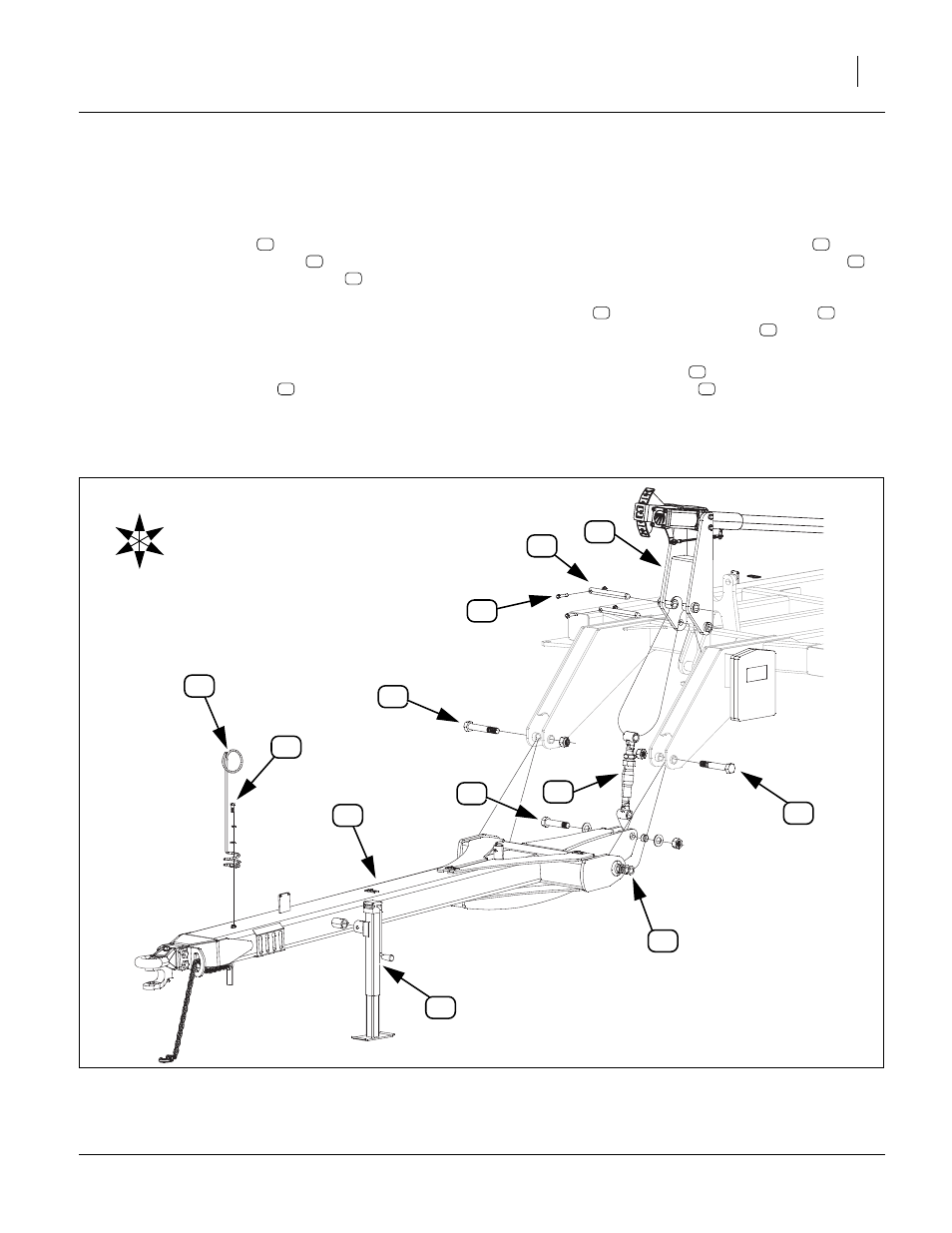
Refer to Figure 8
18. Install hitch assembly
to front of center frame with
the 1
1
⁄
4
” x 8” Gr. 8 hex bolts
provided. Be sure
and install 1
1
⁄
4
” machine washers
as needed on
both sides, to insure a tight fit (be sure and have
same amount on both sides of hitch). Secure with
the 1
1
⁄
4
” top lock nuts. Bolts need to be tightened
down securely on the ball joints but do not torque as
hitch needs to pivot freely.
19. Remove the tongue jack
from its storage location
at rear of hitch and install it on the jack stub at the
front of the hitch frame to support the front side of
hitch.
20. Connect the bottom of leveling turnbuckle
to rear
of hitch with 1
1
⁄
4
” x 6” Gr. 5 special thread bolt
,
and 1 nylon lock nut, (do not torque bolt), connect
the top of the turnbuckle to the middle hole of leveler
assembly
with the 1
1
⁄
4
” x 11” hinge pin
,
1
⁄
2
” x
2
5
⁄
8
” Gr. 8 special thread hex bolt
and
1
⁄
2
” top
lock nut.
21. Attach spring hose loop
to front of hitch assembly
with
1
⁄
2
” x 1
1
⁄
2
” hex bolts
,
1
⁄
2
” flat washers,
1
⁄
2
”
lock washers and
1
⁄
2
” nuts.
22. Bolts may be tightened to specs, See “Torque Val-
11
12
13
14
15
16
17
18
19
20
21
12
11
13
17
18
15
U
D
F
B
L
R
12
14
16
19
20
21
Figure 8
Hitch to Frame Assembly
43448