Drill lift/lower (s/n a1057v+), Raising, Raising after transport, parking or storage – Great Plains 3P806NT Operator Manual User Manual
Page 24: Raising for transport, parking or storage
20
3P806NT
Great Plains Manufacturing, Inc.
151-143M
2011-12-20
Drill Lift/Lower (s/n A1057V+)
(applies to drills with serial numbers A1057V+
For serial number A1056V-, see page 21)
Raising and lowering the drill relies on the tractor 3-point
lift arms in front, and hydraulic lift-assist cylinder at rear.
When setup for field use, the hitch and lift circuits may be
operated in any order, or simultaneously. Both, however,
must be lowered for planting, and the lowered hitch
height must be as established at step 14 on page 16.
Raising
1.
Raise the tractor 3-point lift arms fully.
2.
Activate the lift circuit lever to Extend the lift-assist
cylinder fully. Set circuit to Neutral.
Crushing Hazard:
Rely on circuit Neutral to hold the drill raised only for field
turns. Use parking stands and lock channel for all other raised
operations, transport, parking, maintenance and storage.
Raising after Transport, Parking or Storage
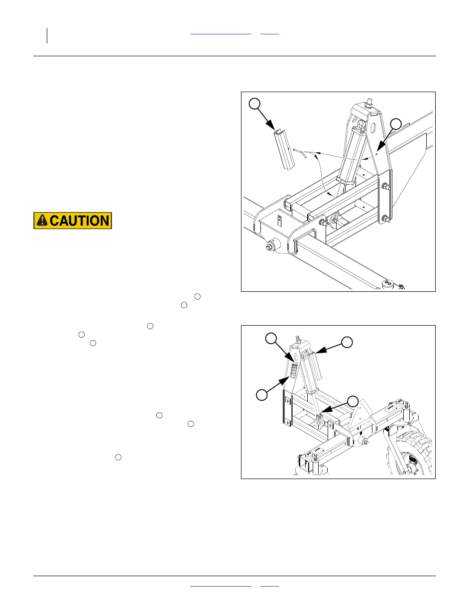
Refer to Figure 11 and Figure 12
3.
If raising for planting, remove lock channel
from
lift-assist cylinder. Store in the pin hole
of the right
side of lift assist weldment.
4.
Install stroke control spacers
. Remove needed set
from rod
on lift-assist weldment and clamp around
cylinder rod
. Use a locally developed spacer
combination (see page 17).
Raising for Transport, Parking or Storage
Refer to Figure 11 and Figure 12
5.
If raising for transport or storage, set lift circuit to
neutral to hold at raised. Set tractor parking brake
and shut off tractor.
6.
Remove stroke control spacers
from lift-assist
cylinder. Store spacers on weldment rod
.
Note: If recently developed or changed, make a note of
the combination removed.
7.
Install lock channel
on cylinder rod. Secure with
pin.
8.
Re-start tractor. Slowly move the lift circuit lever to
Retract, allowing the cylinder to settle on the lock
(and relieving pressure from the hydraulic system).
Figure 11
Lock Channels (s/n A1057V+)
31920
1
2
1
2
Figure 12
Stroke Control Spacers (A1057V+)
32057
1
5
3
4
3
4
5
5
4
1