Stroke control spacers (s/n a1057v+), Check level, Stroke control spacers (s/n a1057v+) check level – Great Plains 3P806NT Operator Manual User Manual
Page 21
Great Plains Manufacturing, Inc.
Preparation and Setup
17
2011-12-20
151-143M
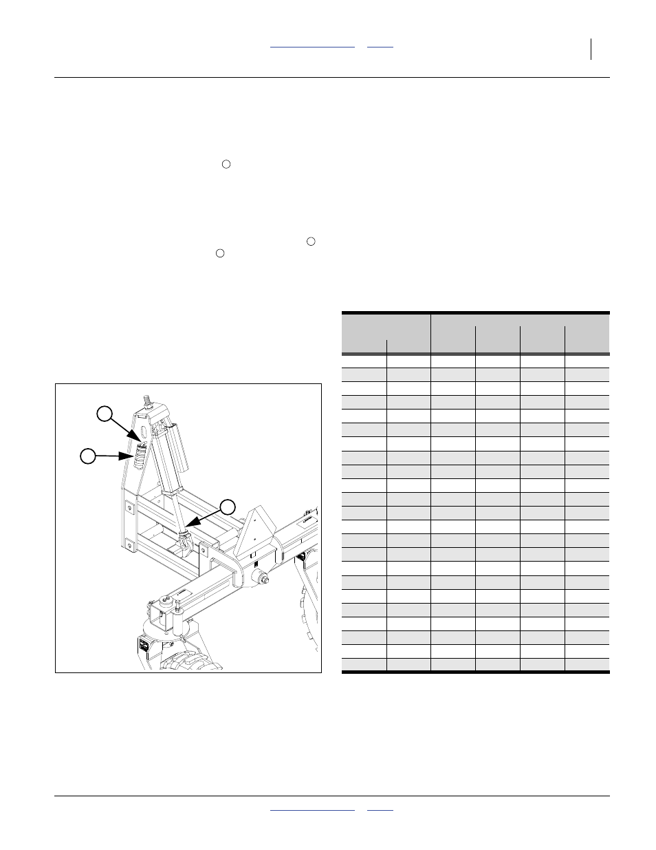
Stroke Control Spacers (s/n A1057V+)
(Applies to drills with serial numbers A1057V+
For serial number A1056V-, see page 18.)
The height of the drill at rear (when lowered) is adjusted
with a set of stroke control spacers
(part no.
810-442C) included with the drill. Five snap-around
spacers are stored on the storage rod for a combined
length of 6
1
⁄
2
inches (165 mm).
Refer to Figure 7 and the table in Figure 8
15. Remove the desired combination of stroke control
spacers from the lift-assist weldment storage rod
and install on the cylinder rod
. There is no factory
recommendation for this, as it depends on the tractor
used.
Check Level
16. Lower drill until the cylinders rest on the stroke
control spacers. See “Drill Lift/Lower (s/n
A1057V+)” on page 20.
17. Pull drill forward to put coulters and openers in
ground, and assure that lift-assist casters are in
trailing position. Set tractor brakes.
18. When correct level has been achieved, set a stop,
lock or reference indicator on the tractor’s hitch
control to prevent lowering below drill-level.
19. Check level of frame front-to-rear. If not level, adjust
the rear height with the stroke control spacers. If
changed, re-check front tool bar height, and
re-adjust tractor 3-point lift arms. Repeat until level.
4
5
6
Spacer Sizes
Stack Length
1 in.
1¼ in.
1½ in.
1¾ in.
inches
mm
25 mm
32 mm
38 mm
44 mm
1.00
25
1
1.25
32
1
1.50
38
1
1.75
44
1
2.00
51
2
2.25
57
1
1
2.50
64
1
1
2.75
70
1
1
2.75
70
1
1
3.00
76
1
1
3.25
83
2
1
3.25
83
1
1
3.50
89
2
1
3.75
95
2
1
3.75
95
1
1
1
4.00
102
1
1
1
4.25
108
1
1
1
4.50
114
1
1
1
4.75
121
2
1
1
5.00
127
2
1
1
5.25
133
2
1
1
5.50
140
1
1
1
1
6.50
165
2
1
1
1
Figure 8
Stroke Control Spacer Combinations
28359
Figure 7
Stroke Control Spacers (A1057V+)
32057
Note: If planting in rolling terrain, it may be necessary
to adjust the lift assist cylinders manually with the
tractor hydraulics to allow the machine to float
backwards.
6
5
4